


RMV Operations Manual Revision Copyright illunis LLC, 2014
Page 10
C
ha
pt
er
1
:
O
ver
vie
w
R
ug
ged
Mac
hin
e V
isi
on
Introducing:
Rugged Machine Vision
The RMV is our newest line of area scan cameras for industrial machine vision and
photography. Designed from the ground up with the latest technologies, this line of cameras rep-
resents a new standard in digital imaging. The RMV product line builds on the popular XMV prod-
ucts by adding 14 bit analog sampling and 12bit data paths, advanced triggering and CCD readout
control, built in detectors that analyze the camera’s performance, image processing to remove
sensor defects, correct for flat field effects, and on screen tools for analyzing line/columns as well
as text overlay. No longer are you required to depend on custom tools to setup and analyze your
demanding imaging systems.
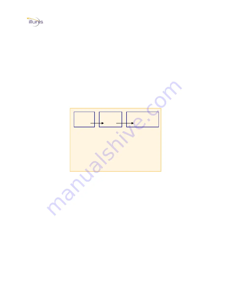
RMV Camera Architecture
The RMV camera is based on a modular design which allows for many different image
sensors and output formats to be implemented. Through combinations of three different PCB’s
many different cameras can be created. Each sensor is supported with its own unique circuit
board which contains the circuitry needed to drive the sensor and output the digital image data.
The Image Processing PCB is common to all cameras and supports the advanced features of the
RMV. The data format and power PCB provides the camera link and other signal outputs. From
these PCB combinations illunis can manufacture a family of advanced digital cameras.
1 or 2 tap Sensors:
The RMV supports any
sensor with one, two or
four video taps. The
Truesence
interline
transfer CCD’s are
supported with pro-
grammable tap opera-
tion so you can select
the best output option
for your application.
The built in image
detectors include tap
boundary
measure-
ment and active tap
balancing logic to in-
sure that the two taps
gain and offset match
as close as possible.
14 bit ADC’s and data path with Tap Reorder:
The RMV supports full 14 bit signal sam-
pling and 12bit data paths throughout the signal processing path. This insures that the maximum
signal quality is preserved in the processing chain. The tap data is reordered within the RMV to a
single raster. Each ADC has programmable gain and programmable active black clamp.
Image Signal Processor (ISP):
At the heart of the RMV camera is a very powerful image
signal processor that is implemented with a FPGA. The ISP provides all of the sensor control as
well as image processing and diagnostics. The ISP is capable of processing all of its functions in
a single pixel clock cycle at up to 80 million pixels per second. Any area sensor to 8Kx8K is sup-
ported.
Micro Processor (uP) with FLASH data storage:
Supporting the ISP is an advanced mi-
croprocessor. The uP is paired with FLASH memory that stores the data for the ISP. The uP also
monitors the operation of the RMV and tracks the camera temperature and performance parame-
ters.
Communication Interface and GUI:
Control of the RMV is through a military spec packed
based command protocol. The operation of the RMV is represented as modes which can be read
as status and written as commands. Packets are error checked and reply with ACK/NACK’s A
Graphical User Interface (GUI) is included as source code to speed integration. The GUI allows
for control of the camera with a standard windows interface.
Signal
Processing
PCB
Sensor
PCB
Data Format and
Power
PCB
RMV Camera Modularity Options
* Coming in 2004
Sensors Supported
Truesence CCD:
All 5.5 um Sensors
All 7.4 um Sensors with 4
tap readout.
Data Formats Supported
Camera Link Base Mode
8/10/12 bits per tap
1 or 2 channels


