


80
HDK-99 1803 VER1 (E)
5.1 Settings Using Switches on the Camera
Allocating Functions to the P.FUNC Switch
The user can select a function to allocate to the P.FUNC (Personal Function) switch. By allocating the function used most
frequently, the user can easily operate the camera.
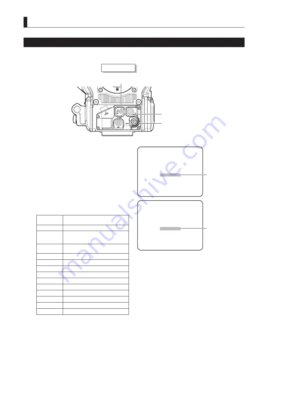
Camera front view
Rotary pulse switch
P.FUNC switch
SET button
1
Set the P.FUNC switch on the front of the camera
to SEL.
The selection display flashes.
2
Turn the rotary pulse switch to select the function
to be allocated, and press the SET button.
The selected function is allocated to the P.FUNC
switch.
The following table shows the functions that can be
allocated to the P.FUNC switch:
Selection
Display
Function
SKIN DTL
Turns ON/OFF the SKIN DTL function
IRIS+CORR
Turns ON/OFF the mode to adjust the
iris by approxi1/2 STOP when
AUTO IRIS is set
IRIS++CORR
Turns ON/OFF the mode to adjust the iris
by +1 STOP when AUTO IRIS is set
AUTO KNEE
Turns ON/OFF the AUTO KNEE function
SOFT DTL
Turns ON/OFF the SOFT DTL function
SCENE-1
Turns ON/OFF scene file 1
SCENE-2
Turns ON/OFF scene file 2
SCENE-3
Turns ON/OFF scene file 3
SCENE-4
Turns ON/OFF scene file 4
SCENE-5
Turns ON/OFF scene file 5
SCENE-6
Turns ON/OFF scene file 6
SCENE-7
Turns ON/OFF scene file 7
SCENE-8
Turns ON/OFF scene file 8
3
Set the P.FUNC switch to ON.
The allocated function is now activated.
Note:
Setting the P.FUNC switch to OFF will turn the allocated function OFF.
①
The selection display
flashes.
②
The allocated function
is displayed.
P.FUNC SW ENTRY
NO ENTRY
P.FUNC SW ENTRY
SKIN DTL
Summary of Contents for FA-97A
Page 1: ...HIGH DEFINITION CAMERA SYSTEM HDK 99 FA 97A OPERATION MANUAL...
Page 2: ......
Page 17: ...1 OUTLINE...
Page 18: ......
Page 24: ......
Page 26: ......
Page 27: ...2 NAME and FUNCTION...
Page 28: ......
Page 47: ...3 INSTALLATION and CONNECTION...
Page 48: ......
Page 50: ...34 HDK 99 1803 VER1 E...
Page 52: ......
Page 54: ......
Page 70: ......
Page 71: ...4 OPERATION...
Page 72: ......
Page 88: ......
Page 89: ...5 CAMERA SETTINGS and ADJUSTMENT...
Page 90: ......
Page 126: ......
Page 127: ...6 TROUBLE SHOOTING and MAINTENANCE...
Page 128: ......
Page 138: ......
Page 139: ...7 SPECIFICATIONS...
Page 140: ......
Page 144: ...128 HDK 99 1803 VER1 E 7 2 External Dimensions Diagram Left View 94 3 7 1 337 5 270 5...
Page 160: ......
Page 162: ......
Page 164: ......
Page 165: ......