Removing
and
Replacing
the Apollo
GX
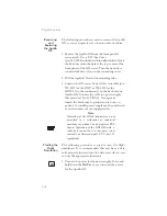
The following procedure is used to remove the Apollo
GX so you can operate it at a location of your choice.
1. Remove the Apollo GX from the front panel of
your aircraft. Use a 3/32” hex driver
(p/n 998-0048 included with installation kit). Insert
the hex driver into the hole at the top, center of the
front panel of the GX-series. Turn the hex driver
counterclockwise to loosen the connecting screw.
2. Pull the Apollo GX out of its mounting tube.
3. Connect the GX-series Power Cable Assembly (p/n
500-4027 for the GX55 or 500-4026 for the
GX50/60) to the connector(s) on the back of your
Apollo GX. Connect the cable to a power supply
that provides 10 to 40 VDC @ 1A or greater.
Attach the black wire to ground and red wire to
positive. A suitable power supply may be purchased
at an electronics or auto supply retailer.
Note
Operation of the GX60 transmitter is not
permitted in a residential or industrial
environment without an appropriate FCC
license. Operation of the GX50/60 with a
serial port connected to a computer is not
currently authorized under FCC part 15
regulations.
Starting the
Flight
Simulation
The following procedure is used to start the flight
simulation. It is recommended that you have a data
card properly inserted into the data card slot so you
can use the appropriate functions.
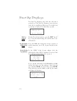
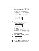
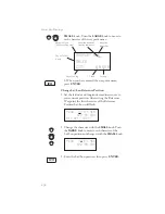
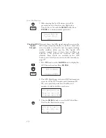
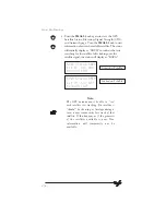
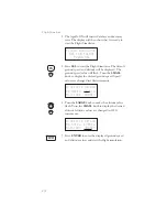
1. Turn on the power for the power supply. Press and
hold down the NAV key as you turn on the power
for the Apollo GX.
256
Flight Simulator
NAV
Summary of Contents for Apollo GX 50
Page 1: ......
Page 17: ...I 270 K 270 L 270 M 270 N 271 O 272 P 272 R 272 S 273 T 273 U 274 V 274 W 274 xv ...
Page 18: ...xvi ...
Page 88: ...Notes 70 Moving Map Functions ...

