background image

Configuration via Management Software 

SNMP Module 

50 

Configuring the time server 

To configure a time server, proceed as follows: 
1.  Select 

System Settings > Date and Time

 in the task area. 

2.  Click the 

Activate Edit Mode

 menu item in the toolbar. 

3.  Activate the 

SNTP

 checkbox to enable the SNTP option. 

4.  Enter the IP address of your SNTP server into the 

SNTP Server

 field. 

5.  Select your time zone in the 

Time Zone

 field. 

6.  Click the 

Apply

 button to confirm your settings. 

7.  Click the 

Deactivate Edit Mode

 menu item in the toolbar. 


NOTICE 

A change in system-relevant parameters (e.g. change of the SNTP server) is immediately displayed in the 

management software. To initialize system-relevant configuration changes on the SNMP module, the 

SNMP module must be restarted. The restart of the SNMP module may take several minutes, and the 

SNMP module is not available during the restart. 
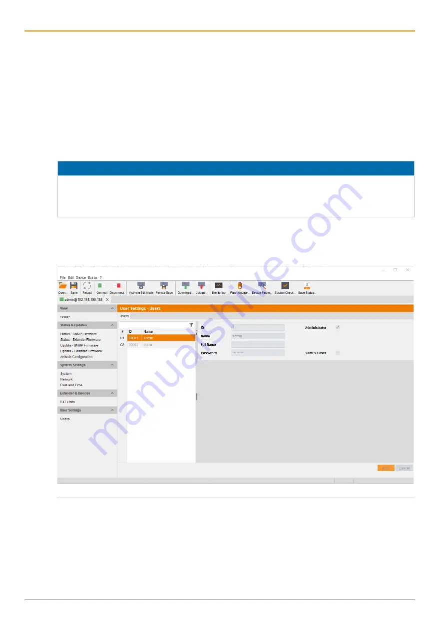
 

5.5  User Settings 

User settings and permissions are set in this menu. By default, two users are set. It is not intended to 
create additional users. 


Fig. 34 

Management software menu 

User Settings - Users


Summary of Contents for 474-SNMP

Page 1: ...Dokument 474 SNMP Rev02 00_en Firmware version 1 02 Edition 2021 02 08 Software version 4 0 0 0 USER MANUAL SNMP Module 474 SNMP 474 SNMPV3 ...

Page 2: ...erences between the various models are clearly described The manufacturer reserves the right to change specifications functions or circuitry of the series described here without notice Information in this manual can be changed expanded or deleted without notice You can find the current version of the manual in the download area of our website Copyright 2021 All rights reserved This manual may not ...

Page 3: ...6 Slot Chassis Draco vario 474 BODY6BPF 17 3 8 3 21 Slot Chassis Draco vario 474 BODY21 4U 17 3 9 Device Views SNMP Modules 18 3 9 1 Module 474 SNMP 18 3 9 2 Module 474 SNMPv3 18 3 10 Status Indication of the Chassis 19 3 10 1 6 Slot Chassis Draco vario 474 BODY6BP 19 3 10 2 6 Slot Chassis Draco vario 474 BODY6BPF 19 3 10 3 21 Slot Chassis Draco vario 474 BODY21 4U 20 3 11 Status Indication of the...

Page 4: ...g the SNMP Module 37 5 4 2 Setting the Network Configuration 38 5 4 3 Setting the Syslog Function 40 5 4 4 Setting the SNMP Function 43 5 4 5 Setting the Date and Time 49 5 5 User Settings 50 5 6 Extender Settings 52 5 6 1 Extender Type 53 5 6 2 Firmware Version 54 5 6 3 Parameters 55 5 6 4 USB HID Ghosting 60 5 6 5 EDID 61 5 7 Saving Configuration 62 5 7 1 Saving the Current Configuration to the ...

Page 5: ... Interfaces 94 7 1 1 Mini USB 94 7 1 2 RJ45 Network 94 7 1 3 RS232 Serial 94 7 2 Connector Pinouts 95 7 2 1 Mini USB Type B 95 7 2 2 RJ45 Netzwerk 95 7 2 3 D Sub 9 Serial RS232 95 7 2 4 Power Supply 95 7 3 Power Supply Current Draw and Power Consumption 96 7 3 1 Power Supply of the Chassis AC 96 7 3 2 Current Draw and Power Consumption of the SNMP Modules 96 7 4 Environmental Conditions and Emissi...

Page 6: ...Table of Contents SNMP Module 6 12 EU Declaration of Conformity 103 13 Glossary 104 14 Table of Figures 105 ...

Page 7: ... manufacturer for an effective utilization of the device potential 1 2 Spellings Uniform spellings are used in this manual for better readability or easier assignment The following spellings are used for products Product Description Draco tera Tool Management software Source Computer CPU Sink Console monitor keyboard mouse The following spellings are used for keyboard commands Keyboard command Des...

Page 8: ...laration of Conformity For information about the Declaration of Conformity refer to chapter 12 page 103 A copy of the original product specific EU Declaration of Conformity can be provided upon request For contact details see page 2 of this manual ...

Page 9: ...ice only in dry indoor environments Use the device only in a room with adequate ventilation For rack mount installations at least 0 5 RU rack unit is required above the KVM extender for ventilation Do not place the power supply units directly on top of the device Existing ventilation openings on the device must always be free If installing the device under the table place the device at a sufficien...

Page 10: ...CE The cable plugs on the device side can contain a lock In the event of a necessary quick and complete disconnection from external electric circuits remove all corresponding cable plugs from the socket or set the power switch of the power outlets if available to the Off position ...

Page 11: ...ions for the length and type given in this manual 3 2 Access Options You have following options to configure and operate the KVM Extender Access option Description Draco tera Tool The Draco tera Tool management software is available as a single executable program file desktop and app version that does not require a separate installation The management software can be downloaded from the link https...

Page 12: ...parts part A and B one on the left and one on the right see Fig 1 Fig 1 KVM Extender pair with CPU Unit and CON Unit 1 KVM Extender pair 2 Extender module or add on module optional 3 Extender module 4 Part A of the CPU add on module optional 5 Part B of the CPU add on module optional 6 Chassis 7 CPU Unit 8 CON Unit 9 Part A of the CON add on module optional 10 Part B of the CON add on module optio...

Page 13: ...d cables The CON Unit is connected to the console monitor keyboard and mouse The CPU Unit and the CON Unit communicate with each other through the interconnect cables Fig 4 Installation example Single Head with SNMP module in the CPU Unit 1 Source computer CPU 2 CPU Unit with SNMP module 3 Interconnect cable 4 CON Unit 5 Console monitor keyboard mouse Example of use installation of an SNMP module ...

Page 14: ...slot 21 The transmission of the traps is unencrypted SNMP v1 474 SNMPv3 SNMP module for sliding in into the chassis 474 BODY6BP slot 5 474 BODY6BPF slot 5 and 474 BODY21 4U slot 21 The transmission of the traps is unencrypted SNMP v3 3 5 Accessories Chassis Type Description 474 6RMK 19 Rackmount Ears for Draco vario 6 slot chassis 474 VPLATE Mounting plate for 2 4 6 slot chassis 474 BRACKET Wall T...

Page 15: ... delivery contains the following items Product type Scope of delivery 474 SNMP 1x Module 474 SNMP 1x Serial control cable 474 SNMPV3 1x Module 474 SNMPV3 474 BODY6BP 2x country specific power cord per chassis 474 BODY6BPF 474 BODY21 4U If anything is missing please contact your dealer ...

Page 16: ...s the power consumption of the connected peripherals must be added Note the maximum power consumption of the chassis see chapter 7 3 1 page 96 3 8 1 6 Slot Chassis Draco vario 474 BODY6BP Fig 6 Interface side chassis 474 BODY6BP 1 Slot 1 2 Slot 2 3 Slot 3 4 Slot 4 5 Slot 5 6 Slot 6 Fig 7 Rear view chassis 474 BODY6BP 1 Power supply AC standard 2 Power supply AC redundancy optional 3 Grounding ...

Page 17: ... Slot 6 7 Power supply AC standard 8 Power supply AC redundancy optional 3 8 3 21 Slot Chassis Draco vario 474 BODY21 4U Fig 9 Interface side chassis 474 BODY21 4U 1 Slots 1 to 21 from left to right Fig 10 Rear view chassis 474 BODY21 4U 1 Power supply AC redundancy 2 Power supply unit redundancy optional 3 Power supply unit standard 4 Power supply AC standard ...

Page 18: ...of the chassis later than March 2014 Slot 21 474 BODY21 4U 3 9 1 Module 474 SNMP Fig 11 Interface side 474 SNMP 1 RS232 serial D Sub 9 female socket 2 Input Output RJ45 network connection This module works with the unencrypted SNMPv1 standard 3 9 2 Module 474 SNMPv3 Fig 12 Interface side 474 SNMPv3 1 Input Mini USB service 2 Input Output RJ45 network connection This module works with the encrypted...

Page 19: ...scription 3 and 4 AC Input 2x green Power supply voltage available 1x green 1x red No redundant power supply voltage available 2x off No power supply voltage available 3 10 2 6 Slot Chassis Draco vario 474 BODY6BPF Fig 14 Interface side chassis 474 BODY6BPF status LEDs 1 Status LED for power supply 1 2 Status LED for power supply 2 Status LEDs for Power Supply Voltage Pos LED Status Description 1 ...

Page 20: ...y 2 Status LED for power supply standard 3 Fault LED for power supply standard Status LEDs for Power Supply Voltage Pos LED Status Description 1 3 AC Input green Off Power supply voltage not available On Power supply voltage available 2 4 Fault LED red On The input voltage of the power supply unit is too low The output voltage of the power supply unit too high Permissible power supply temperature ...

Page 21: ...e flashing Registration of the SNMP module has started Red flashing Registration in progress Green flashing Operating condition Green SNMP module de registered 4 Status 2 White SNMP module is in registration process Due to variations in LED type white might also appear as light purple or light blue Status LEDs of the network port Pos LED Status Description 2 Activity status green Off No network co...

Page 22: ...ion of the SNMP module has started Red flashing Registration in progress Green flashing Operating condition Green SNMP module de registered 2 Status 2 White SNMP module is in registration process Due to variations in LED type white might also appear as light purple or light blue Status LEDs of the network port Pos LED Status Description 3 Link status orange Off No network connection available or n...

Page 23: ...g functions are available in most of the menus Button Function Apply Confirm changes temporary storage of the active configuration in the volatile memory of the SNMP module Cancel Reject changes NOTICE Possible loss of changes By clicking the Apply button changes are applied to the active configuration and saved in the volatile memory of the SNMP module In the event of a sudden power failure these...

Page 24: ...gement Software Toolbar Some functions are only available if a connection to the SNMP module has been established online mode The respective functions are marked here with online Fig 19 Management software toolbar 1 Load locally saved configuration 2 Save configuration locally 3 Update configuration 4 Connect to SNMP module switches to online mode 5 Disconnect from SNMP module switches to offline ...

Page 25: ...tables Jump from tables into the previous field Various functions within the menus in the menu bar can be executed with the provided keyboard commands e g press Ctrl S to execute Save that are listed to the right of the respective menu item 3 12 5 Management Software Reload Options The information shown in the management software can be reloaded in different ways Press the F5 key on the used keybo...

Page 26: ...t points downwards Cancel sort Click with the primary mouse button once or twice on the head of the sorted column The displayed arrow disappears 3 12 8 Management Software Filter Function Lists and tables in the management software offer a filter function that supports a fast and smooth search The filter entry field is located above the header An active filter is indicated by a green filter symbol...

Page 27: ...ng ports are used by the KVM Extender depending on the configuration and must be released at the security gateway if necessary The ports must only be released if you want to use the respective function Function Port DNS 53 SNTP 123 UDP SNMP 161 162 both UDP Syslog 514 UDP API 5555 TCP 5565 for SSL Broadcast 5556 UDP 5566 for SSL 4 2 Installing the SNMP Module NOTICE The SNMP module can only be ins...

Page 28: ...ps github com ojdkbuild ojdkbuild Management software desktop version Draco tera Tool Downloaded from https www ihse de software Network connection Available between computer and SNMP module Contact your system administrator concerning JRE and network connection If you want to use the management software as an app version the following requirements must be fulfilled Computer Software Network Requi...

Page 29: ...ion between computer and the SNMP module that is not primarily used for streaming audio or video data Connect the network cable to the RJ45 ports of computer and SNMP module 4 3 2 Starting Management Software Open the management software by a double click on the program icon on the desktop or the file in the directory The management software starts in offline mode Fig 20 Management software landin...

Page 30: ...ings of the SNMP module 474 SNMP IP Address 192 168 100 99 and DHCP is deactivated 474 SNMPV3 IP Address 192 168 100 99 and DHCP is activated 3 Enter the username and password of the administrator see chapter 5 5 page 50 4 Click the Login button to confirm your entries Fig 21 Management software dialog Connect The data must be entered each time the network connection is re established Alternativel...

Page 31: ...not available during the restart 5 1 Configuring in Online Mode Configurations and system settings can be edited via management software in online mode with an active connection between SNMP module and management software Hereby the following steps are necessary 1 Connect the management software with the SNMP module When connecting the first time the manufacturer specific configuration Factory Set...

Page 32: ...e SNMP module When connecting the first time the manufacturer specific configuration Factory Settings saved on the SNMP module is loaded into the management software 2 Download the configuration 3 Disconnect the management software from the SNMP module The configuration is now editable 4 Make any edits in the configuration and system settings 5 Click the Apply button to confirm the changes The cha...

Page 33: ...this data can be saved in the default settings Fig 22 Management software menu Extras Options Default Settings The following parameters can be configured Option Description IP Hostname Default IP address or host name of the SNMP module for establishing a connection User Default username for establishing a connection Configuration Directory Default directory for configuration files Firmware Directo...

Page 34: ...ize and Tooltip in the Toolbar The font size can be set in this menu and the display of tooltips for the toolbar can be activated 1 Select Extras Options in the menu bar and open the Style tab 2 Select the desired font size 3 Click the Show Toolbar Button Text checkbox A tooltip is displayed when hovering over a menu item in the toolbar 4 Select the color theme for the management software default ...

Page 35: ...rset must match the selected language to ensure correct representation 1 Select Extras Options in the menu bar and open the Language tab 2 Select the desired language within the management software and the corresponding charset 3 Click the Ok button to confirm your changes 4 Close the management software and restart it Fig 24 Management software menu Extras Options Language ...

Page 36: ...t Extras Options in the menu bar and open the Miscellaneous tab 2 Activate the Device Finder on startup checkbox After restarting the SNMP module the Device Finder appears 3 Click the Ok button to confirm your changes 4 Close the management software and restart it Fig 25 Management software menu Extras Options Miscellaneous The other shown options are provided when using a matrix see matrix user m...

Page 37: ...n Device Text Enter the device name of the SNMP module default SNMP 01 The device name is used as the host name in the network Name Text Enter the name of the configuration that is used to save the current settings default Standard Info Text Additional text field to describe the configuration default Factory settings To define parameters for the SNMP module proceed as follows 1 Select Configuratio...

Page 38: ...Management software menu System Settings Network General The following parameters can be configured Network Settings Field Entry Description DHCP Activated The network settings are automatically supplied by a DNS server Note If DHCP is activated and there is no physical network connection available the boot times might increase Deactivated Function not active default IP Address Byte Input of the I...

Page 39: ...tion for API management software API management software and SNMP module communication Deactivated Function not active default To set parameters for the network configuration proceed as follows 1 Select System Settings Network in the task area 2 Click the Activate Edit Mode menu item in the toolbar 3 Modify the desired settings 4 Click the Apply button to confirm your entries 5 Click the Deactivat...

Page 40: ...etwork Syslog The following parameters can be configured Field Entry Description Enable Syslog Activated Syslog server to query status is active Deactivated Function not active default Syslog Server Byte Input of the IP address of the syslog servers in the form 192 168 1 1 Port Byte Input of the syslog ports default 514 Log Level DEB Activate debug messages in syslog default N Note The debug messa...

Page 41: ...ions To set or activate the presetting proceed as follows 1 Select Extras Options in the menu bar and open the Syslog tab 2 Enter the appropriate data 3 Click the Ok button to confirm your entries 4 Close the management software and restart it Fig 29 Management software menu Extras Options Syslog The following options are available Option Description Log File Directory Default directory to store t...

Page 42: ...n for errors Autostart When starting the management software the syslog function will be started in the background Open Monitoring Tab When starting the management software the monitoring tab will be opened When reaching the maximum log file size a new log file will be created When reaching the maximum number of log files the oldest logfile will be overwritten with the new information ...

Page 43: ... conformal standard Two SNMP servers can be used at the same time NOTICE When using SNMP monitoring for reasons of access security the use of a dedicated network according to the IT Grundschutz catalog is recommended The read only community for the MIB file is draco NOTICE For an activation of the SNMP agent function or the SNMP server function a restart of the SNMP module is necessary Fig 30 Mana...

Page 44: ... the SNMP agent to the SNMP server Deactivated No traps are sent to the den SNMP server default SNMP Server Byte Input of the IP address of the SNMP server in the form 192 168 1 1 Port Numerical Input of the SNMP port default 162 If you activate the checkbox Enable Traps the following traps are activated by default Field Description Temperature Notification of the temperature of the power supply u...

Page 45: ...e SNMP server under SNMP Server 6 Click the Apply button to confirm your changes 7 Click the Deactivate Edit Mode menu item in the toolbar Setting up SNMP options Presets for an SNMPv3 user can be set up for the computer on which the management software is operated and are set in this menu The following options are available Option Description Port Input of the SNMP port default 162 Log File Direc...

Page 46: ...e the presetting proceed as follows 1 Select Extras Options in the menu bar and open the SNMP tab 2 Modify the desired settings 3 Click the Ok button to confirm your entries 4 Close the management software and restart it Fig 31 Management software menu Extras Options SNMP ...

Page 47: ... data username and password in both settings are identical see chapter 5 5 page 50 To configure the login data for an SNMPv3 user at the SNMP server proceed as follows 1 Select Extras Options in the menu bar and open the SNMP tab 1 Click the Manage SNMPv3 Users button A list appears with already created SNMPv3 users 2 Click the Add User button A dialog window appears 3 Enter the required data and ...

Page 48: ...username not changeable default snmp Authentication Protocol Only SHA protocol no selection available Authentication Password Authentication password for the SNMPv3 user case sensitive input of minimum 8 characters up to 16 characters Privacy Protocol Only DES protocol no selection available Privacy Password Must be identical to the password of the authentication password ...

Page 49: ...ttings Date and Time The following parameters are pre configured or can be configured SNTP Field Entry Description SNTP Activated Enable network time server synchronization Deactivated Function not active default SNTP Server Byte Input of the SNTP server IP address default 000 000 000 000 Time Zone Region Set your specific time zone default GMT 00 System Time Field Description Date And Time Date a...

Page 50: ...button to confirm your settings 7 Click the Deactivate Edit Mode menu item in the toolbar NOTICE A change in system relevant parameters e g change of the SNTP server is immediately displayed in the management software To initialize system relevant configuration changes on the SNMP module the SNMP module must be restarted The restart of the SNMP module may take several minutes and the SNMP module i...

Page 51: ... parameters can be configured for the SNMPv3 user Field Entry Description Name Text Username default draco case sensitive input of minimum 8 characters up to 32 characters Full Name Text Optional personal username case sensitive up to 32 characters Password New Password Text User password case sensitive input of minimum 8 characters up to 16 characters Repeat New Password Text Repetition of the us...

Page 52: ...extender in one extender unit Fig 35 Management software menu Extender Devices EXT Units Following parameters are recognized automatically Field Entry Description ID Text Numerical value of the extender ID KVM extenders ID is provided by extender unit Serial No and cannot be changed Name Text Name of the extender unit Port 1 to 21 Slot number of the extender unit depending on the chassis Fixed Wit...

Page 53: ...task area 2 Click the extender unit to be displayed The extender type is displayed on the right side of the working area The Basic column stands for the extender of the selected extender unit The Part A or Part B column stand for the add on module of the selected extender unit Fig 36 Management software menu Extender Devices EXT Units Expert View Extender Type ...

Page 54: ...Click the Activate Edit Mode menu item in the toolbar 3 Click the extender unit to be displayed 4 Click the Firmware Version tab on the right side of the working area The Firmware Version overview is displayed on the right side of the working area Fig 37 Management software menu Extender Devices EXT Units Firmware Version Add on modules are shown together with the associated KVM extender in one ex...

Page 55: ...its in the task area 2 Click the Activate Edit Mode menu item in the toolbar 3 Click the extender unit to be displayed 4 Click the Parameter tab on the right side of the working area 5 Click the Read button A query to read the parameters appears 6 Click the Yes button to confirm the reading Fig 38 Management software menu Extender Devices EXT Units read parameters ...

Page 56: ...ces EXT Units displayed parameters The following functions are available Button Function Open Open locally saved parameters Save As Save parameters locally file Config txt Read Read parameters of the extender unit Transmit Transmit parameters to the extender unit and activate Reset Reset parameters of the extender unit Assign Assign parameters to several extender units at the same time ...

Page 57: ...ansmit button A query for transmission appears 4 Click the Yes button to transmit the modified parameters to the extender unit The progress of the parameter transmission is displayed 5 Click the Close button when the parameter transmission is completed green Fig 40 Management software menu Extender Devices EXT Units transmission finished The parameter transmission is finished 6 Click the Deactivat...

Page 58: ...y to read the parameters appears 6 Click the Yes button to conform the reading 7 Click the Assign button A query to assign the parameters appears 8 Select the extender units the currently displayed parameters should be assign By pressing the Ctrl key at the same time more than one extender unit can be marked 9 Click the button to transmit the selected extender units to the selection To transmit al...

Page 59: ...ig 42 Management software menu Extender Devices EXT Units start parameter assignment The progress of the parameter assignment is displayed 13 Click the Finish button when the parameter assignment is completed green Fig 43 Management software menu Extender Devices EXT Units assignment finished The parameter assignment is finished 14 Click the Deactivate Edit Mode menu item in the toolbar ...

Page 60: ...ick the Yes button to confirm the reading The USB HID ghosting settings are displayed Fig 44 Management software menu Extender Devices EXT Units USB HID Ghosting The following functions are available Button Function Open Open locally saved parameters Save As Save the USB HID ghosting locally file EXT_ID Nr dhg Read Read the USB HID ghosting of the extender unit Transmit Transmit the USB HID ghosti...

Page 61: ...e of the working area 5 Click the Read button A query to read the EDID appears 6 Click the Yes button to confirm the reading The EDID is displayed on the right side of the working area Fig 45 Management software menu Extender Devices EXT Units EDID Button Function Open Open locally saved EDID Save As Save EDID locally file Config txt Read Read EDID of the extender unit Transmit Transmit EDID to th...

Page 62: ...te Save saving the configuration into a local memory Save or Save as uploading the configuration into a storage slot to the SNMP module Upload 5 7 1 Saving the Current Configuration to the SNMP Module By default the last configuration that has been saved in this way will be restored after a restart of the SNMP module To save the current configuration permanently into the SNMP module memory proceed...

Page 63: ...nu bar 2 Enter a name for the configuration 3 Select the directory of the configuration on your storage medium where the configuration should be saved Configurations are always saved with the file extension dtc Fig 47 Management software menu File Save As Locally saved configurations files can be opened in the management software see chapter 5 8 page 64 be uploaded to the SNMP module see chapter 5...

Page 64: ...r 2 Navigate to the location of the configuration file to be opened 3 Click the configuration file to be opened 4 Click the Open button to open the configuration file Fig 48 Management software menu Open The configuration can also be opened via drag drop To do this click on the configuration file hold down the primary mouse button and drag the configuration file into the management software ...

Page 65: ...P address of the SNMP module 3 Enter the username and password of the administrator 4 Click the Next button to display the selection of storage slots Fig 49 Management software menu Upload Connect 5 Under Select Configuration Slot click the storage slot for the configuration default 6 Option To activate the uploaded configuration immediately click the Activate configuration after upload check box ...

Page 66: ...onfiguration via Management Software SNMP Module 66 7 Click the Finish button to save the configuration into the selected storage location Fig 50 Management software menu Upload Select Configuration Slot ...

Page 67: ...query to restart the SNMP module appears 4 Click the Yes button to confirm the restart The connection is disconnected and the SNMP module is restarted The selected configuration is loaded on restart and is shown in the menu as active configuration under Active Configuration in the work area The previously active configuration is overwritten NOTICE The restart of the SNMP module may take several mi...

Page 68: ... in the toolbar An access window appears 2 Enter the IP address of the SNMP module 3 Enter the username and password of the administrator 4 Click the Next button to display the selection of storage location Fig 52 Management software menu Download Connect 5 Under Select Configuration click the storage location of the desired configuration default 6 Click the Finish button to download the selected ...

Page 69: ...point to incomplete parts of the configuration firmware differences duplications or unconnected extenders but without being system critical ERROR red System check revealed errors in the configuration that can have both functional and system critical influences on the system NOTICE If the messages WARNING or ERROR are generated by the system check function the respective problem will be described a...

Page 70: ...Operation SNMP Module 70 Fig 55 Management software report System Check ...

Page 71: ... via broadcast 255 255 255 255 default Input for search within a multicast group multicast address chapter 5 4 2 page 38 Device Name of the device Name Name of the active configuration IP Address Current IP address of the device MAC Address MAC address of the device Type Type of the device To find a device proceed as follows 1 Click the menu item Device Finder in the tool bar 2 For searching withi...

Page 72: ...start the network check proceed as follows 1 Select Extras Network Check in the menu bar A query appears with an input field for the IP address of the SNMP module to be queried 2 Enter the IP address of the SNMP module 3 Click the Start network check button to start the network check Fig 57 Management software query Network Check enter IP address The availability of the ports is shown after a shor...

Page 73: ...ce configuration and the connections to the SNMP module are displayed in this menu Select View SNMP in the task area to display the current connections Fig 59 Management software menu View SNMP Port Color Description Green TC IP Port is connected Red TC IP Port is not connected or not accesible ...

Page 74: ...etwork connection is displayed in this menu Select System Settings Network in the task area to query the network configuration Fig 60 Management software menu System Settings Network General For information about the parameters please see chapter 5 4 2 page 38 ...

Page 75: ...talled SNMP module Serial Number Serial number of the installed SNMP module Version Installed firmware version Date Issue date of the installed firmware version Status Module availability The different modules can be expanded and collapsed by left clicking on the plus and minus symbols in the Name column By clicking on the plus and minus symbol in the upper right corner of the working area you can...

Page 76: ...e Port Number of ports Type Extender type Device Device to which the extender is assigned Version Installed firmware version Date Issue date of the installed firmware version Firmware types to be updated or firmware conflicts are highlighted in color Extender firmware version conflict Manual update of EXTMSD EXTIMSD recommended Wrong module CPU CON mismatch Undefined type The different modules can...

Page 77: ... files and stored locally NOTICE Syslog messages are transmitted via UDP Therefore port 514 within the used network should not be blocked e g by a firewall The procedure for activating the syslog function is described in chapter 5 4 3 page 40 Fig 63 Management software menu Monitoring Syslog To open the syslog monitoring proceed as follows Click the Monitoring menu item in the toolbar The logged s...

Page 78: ...y Messages for a defined severity will be filtered Host Messages for a defined host will be filtered Message Messages with defined text parts will be filtered Filter options are not valid within the locally stored log files Recording function Various options are available for the messages displayed in the syslog log To save the displayed messages filtered or unfiltered click the Save trace button ...

Page 79: ... the toolbar 2 Click the Find tab in the working area The recorded SNMP messages are displayed in the working area 3 Enter a search term in the Find Message search field 4 Click the Find Next button The first message with the entered search term is highlighted 5 Click the Find Next button again to find another message with this search term The next message with the entered search term is highlight...

Page 80: ...f access security the use of a dedicated network according to the IT Grundschutz catalog is recommended The read only community for the MIB file is draco The procedure for activating the SNMP agent or configuring an SNMP server is described in chapter 5 4 4 page 43 Fig 65 Management software menu Monitoring SNMP To open the SNMP monitoring proceed as follows 1 Click the Monitoring menu item in the...

Page 81: ...ty Messages for a defined severity will be filtered Host Messages for a defined host will be filtered Message Messages with defined text parts will be filtered Filter options are not valid within the locally stored log files Recording function Various options are available for the messages displayed in the SNMP log To save the displayed messages filtered or unfiltered click the Save trace button T...

Page 82: ...oolbar 2 Click the Find tab in the working area The recorded SNMP messages are displayed in the working area 3 Enter a search term in the Find Message search field 4 Click the Find Next button The first message with the entered search term is highlighted 5 Click the Find Next button again to find another message with this search term The next message with the entered search term is highlighted Pos...

Page 83: ...y you want to save the status file 3 Click the Next button Fig 67 Management software menu Save Status Choose Directory 4 Click the Anonymize checkbox to anonymize your personal data when saving the status file if necessary not recommended for trouble shooting If you want to use the status file as a backup do not click the Anonymize checkbox 5 Click the Next button to save the status file Fig 68 M...

Page 84: ...ings 7 Click the Next button Fig 69 Management software menu Save Status Save EXT Unit Settings 8 Wait until all steps show green checkmarks and the Saving status successful message is displayed 9 Click the Finish button to finish the saving Fig 70 Management software menu Save Status Save Status ...

Page 85: ... of the status file to be opened 3 Click the status file to be opened 4 Click the Open button to open the status file Fig 71 Management software menu Device Load Status The status can also be opened via drag drop To do so open the file browser navigate to the storage location of the status file click on the status file hold down the primary mouse button and drag and drop the status file into the m...

Page 86: ...ther information about the SNMP module is available e g ID configuration version or status Bit Module status 0 Available 1 Ready 4 Service mode 28 No link status 31 Invalid Bit Power supply status 0 Ok 1 No power supply available 1 Not available Bit Temperatuer status 0 Ok 1 Temperature high 1 Not available ...

Page 87: ...nto standby mode or sleep mode during the update Save your configuration locally before starting the update Proceed an update via direct LAN connection for reasons of network stability The firmware of the SNMP module can be updated in this menu Fig 72 Management software menu Status Updates Update SNMP Firmware The following information is displayed in the working area Option Description Name Modu...

Page 88: ...ate files should be standardly sourced 3 Save the update files in the Firmware Directory Update To update the firmware of the SNMP module proceed as follows 1 Select Status Updates Update SNMP Firmware in the task area All updateable components of the SNMP module are automatically selected and highlighted in green 2 Click the Update button in the lower part of the working area to start the update ...

Page 89: ...s Updates Update Extender Firmware The following information is displayed in the working area Option Description Name Module name Type Type number Cur Version Installed firmware version Upd Version Current firmware version Cur Date Issue date of the currently installed firmware version Upd Date Date of the latest firmware version Status Module availability Firmware types to be updated or firmware ...

Page 90: ...update proceed as follows 1 Save the device status configuration locally see chapter 6 5 page 83 2 If the options settings for the management software have not yet been set Open Extras Options in the menu bar Under Firmware Directory insert in the directory from which the update files should be standardly sourced 3 Save the update files in the Firmware Directory Update NOTICE After the update the ...

Page 91: ...n the menu bar An access window appears 2 Enter the username and password of the administrator 3 Click the Ok button Fig 76 Management software dialog Authentication required A query to shut down the SNMP module appears 4 Click the Yes button to start the shutdown Fig 77 Management software dialog Shut down SNMP Board The current configuration is saved in the permanent memory of the SNMP module an...

Page 92: ...ollows 1 Select Device Advanced Service Restart SNMP Board in the menu bar An access window appears 2 Enter the username and password of the administrator 3 Click the Ok button Fig 78 Management software dialog Authentication required A query to restart the SNMP module appears 4 Click the Yes button to restart the SNMP module Fig 79 Management software dialog Restart SNMP Board The current configu...

Page 93: ...a reset of the SNMP module proceed as follows 1 Select Device Advanced Service Factory Reset Factory Reset in the menu bar An access window appears 2 Enter the username and password of the administrator 3 Click the Ok button to confirm your entries Fig 80 Management software dialog Authentication required A query to reset the SNMP module appears 4 Click the Yes button to reset the device Fig 81 Ma...

Page 94: ...ccording to EIA TIA 568 B 100BASE T with RJ45 connectors at both ends All four wire pairs are used in both directions The cabling is suitable for a full duplex operation For the cable connection to a source computer CPU a crossed network cable cross cable has to be used 7 1 3 RS232 Serial Communication takes place with a transmission speed of up to 115 2 KBaud regardless of the file format The tra...

Page 95: ...nnected 5 GND Black 7 2 2 RJ45 Netzwerk Connector Pin Signal Pin Signal 1 D1 5 Not connected 2 D1 6 D2 3 D2 7 Not connected 4 Not connected 8 Not connected 7 2 3 D Sub 9 Serial RS232 Connector Pin Signal Color 1 Not connected 6 DSR 2 RxD 7 RTS 3 TxD 8 CTS 4 DTR 9 Not connected 5 GND 7 2 4 Power Supply Connector Pin Signal Inside 5 V DC Out side GND ...

Page 96: ...t draw of the extender and additional modules there is also the current draw of the connected peripherals Note the maximum current draw of the housing see chapter 7 3 1 page 96 Product type Maximum current draw Maximum power consumption 474 SNMP 300 mA 1 4 W 474 SNMPV3 510 mA 2 4 W 7 4 Environmental Conditions and Emissions Parameter Value Operating temperature 5 to 45 C 41 to 113 F Storage temper...

Page 97: ...ing box 474 BODY6BP 474 BODY6BPF 2 5 kg 5 5 lb 3 5 kg 7 7 lb 474 BODY21 4U 10 0 kg 22 1 lb 14 5 kg 32 0 lb Module Dimension 474 SNMP 100 g 0 22 lb 474 SNMPV3 100 g 0 22 lb 7 7 MTBF Specific MTBF values mean time between failure can be requested from the manufacturer if required 8 Maintenance The device contains no user serviceable parts inside Do not attempt to open or repair the device Do not att...

Page 98: ... No connection between SNMP module and computer Check the network cable Check the connectors Firewall settings are not correct Release ports for the firewall see chapter 4 1 page 27 Serial device not operational Settings of the serial interface Check baud rate and general settings No serial connection to source Check connection via serial cable No serial connection to end device e g touch screen k...

Page 99: ...jumper 9 2 1 474 SNMP Setting Jumper 1 Switch off the SNMP module disconnect from power supply 2 Set jumper 3 3 Switch on the SNMP module 4 Wait 2 minutes 5 Switch off the SNMP module disconnect from power supply 6 Remove the jumper 7 Switch on the SNMP module The SNMP module has been reset to factory settings incl administrator password and network configuration Fig 84 474 SNMP setting of jumper ...

Page 100: ...per 2 3 Switch on the SNMP module 4 Wait 2 minutes 5 Switch off the SNMP module disconnect from power supply 6 Remove the jumper 7 Switch on the SNMP module The SNMP module has been reset to factory settings incl administrator password and network configuration Abb 1 474 SNMPV3 Jumper 2 setzen 1 SNMP Modul 474 SNMPV3 2 Jumper 2 2 1 ...

Page 101: ...dealer if necessary Issue date of the existing manual Nature circumstances and duration of the problem Components included in the system such as graphic source CPU OS graphic card monitor USB HID USB 2 0 devices interconnect cable including manufacturer and model number Results from any testing you have done 10 2 Shipping Checklist 1 To return your device you need an RMA number Return Material Aut...

Page 102: ...quency energy emission regulations and ensure a suitably high level of immunity to electromagnetic disturbances All power supplies are certified to the relevant major international safety standards 11 2 Product Safety The product safety of the following devices is proven by the compliance to the listed standards Type Standards 474 BODY6BP IEC 62368 1 2014 EN 62368 1 2014 A11 207 UL 62368 1 2014 CA...

Page 103: ...its 2011 65 EU Council Directive on the restriction of the use of certain hazardous substances in electrical and electronic equipment Compliance with the directives is verified by compliance with the following standards EN 55032 2015 EN 55024 2010 A1 2015 EN 61000 3 2 2019 EN 61000 3 3 2013 A1 2019 EN 61000 6 2 2019 EN 62368 1 2014 A11 2017 EN 63000 2018 Oberteuringen January 28 2021 Place Date Ma...

Page 104: ...ect to a source computer CPU Konsole Monitor keyboard and mouse KVM Keyboard video and mouse MTBF Mean Time Between Failure MTBF is measured in power on hours and describes the system reliability Single Head A system with one video connection USB HID USB HID devices Human Interface Device allow users to interact with computers There is no need for a special driver during installation New USB HID d...

Page 105: ...are dialog Connect 30 Fig 22 Management software menu Extras Options Default Settings 33 Fig 23 Management software menu Extras Options Style 34 Fig 24 Management software menu Extras Options Language 35 Fig 25 Management software menu Extras Options Miscellaneous 36 Fig 26 Management software menu System Settings System 37 Fig 27 Management software menu System Settings Network General 38 Fig 28 ...

Page 106: ...ware menu System Settings Network General 74 Fig 61 Management software menu Status Updates Status SNMP Firmware 75 Fig 62 Management software menu Status Updates Status Extender Firmware 76 Fig 63 Management software menu Monitoring Syslog 77 Fig 64 Management software menu Monitoring Syslog example for search result 79 Fig 65 Management software menu Monitoring SNMP 80 Fig 66 Management software...

Page 107: ...SNMP Module Table of Figures 107 Fig 83 Interface side SNMP modules failure indication 98 Fig 84 474 SNMP setting of jumper 3 99 ...

Reviews: