49
ifm
Device Manual AS-i IO-Link-Gateway (AC5225) Firmware V1.16
2017-11-20
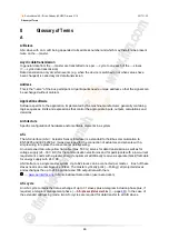
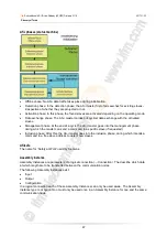
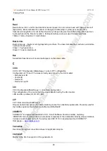
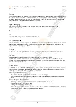
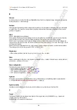
Glossary of Terms
>
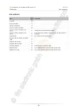
CTT
e.g. CTT2 = Combined Transaction Type 2
→
Combined transaction – Use of analogue channels in the gateway depending on the slave profile
>
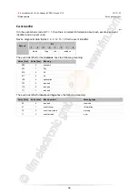
Cycle time
This is the time for one cycle. The following happens:
PLC cycle: The PLC program performs one complete run.
AS-i cycle: all AS-i slaves are updated (5...10 ms).
The cycle time mainly depends on the AS-i slaves involved in the data exchange. Message errors
and management phase may extend the cycle time (
no constant cycle time).
>
Cyclic data transmission
Data are transmitted to one slave at a time by the master once per cycle.
>
Cyclical polling
AS-i master cyclically polls the data of all
→slaves in the →bus (see above). The data is updated in
the
→master after max. 5 ms. If →A/B slaves are used, the →cycle time can be extended to 10 ms.
>
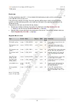
D
Data image (AS-i)
See
→process image; sum of all digital and analogue input and output data.
As regards the time, the data image represents the current condition of each individual slave and NOT
a consistent image of the entire AS-i network at an exact point in time.
>
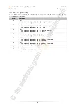
Data type
Depending on the data type, values of different sizes can be stored.
Data type
min. value
max. value
size in the memory
BOOL
FALSE
TRUE
8 bits = 1 byte
BYTE
0
255
8 bits = 1 byte
WORD
0
65 535
16 bits = 2 bytes
DWORD
0
4 294 967 295
32 bits = 4 bytes
SINT
-128
127
8 bits = 1 byte
USINT
0
255
8 bits = 1 byte
INT
-32 768
32 767
16 bits = 2 bytes
UINT
0
65 535
16 bits = 2 bytes
DINT
-2 147 483 648
2 147 483 647
32 bits = 4 bytes
UDINT
0
4 294 967 295
32 bits = 4 bytes
REAL
-3.402823466 • 10
38
3.402823466 • 10
38
32 bits = 4 bytes
ULINT
0
18 446 744 073 709 551 615
64 Bit = 8 Bytes
STRING
number of char. + 1
Summary of Contents for AC5225
Page 64: ......

