


KINO-DH610
Page 44
Step 4:
Orientate the CPU properly.
The contact array should be facing the CPU
socket.
Step 5:
Correctly position the CPU.
Match the Pin 1 mark with the CPU edge on the
CPU socket.
Step 6:
Align the CPU pins.
Locate pin 1 and the two orientation notches on the CPU.
Carefully match the two orientation notches on the CPU with the socket
alignment keys.
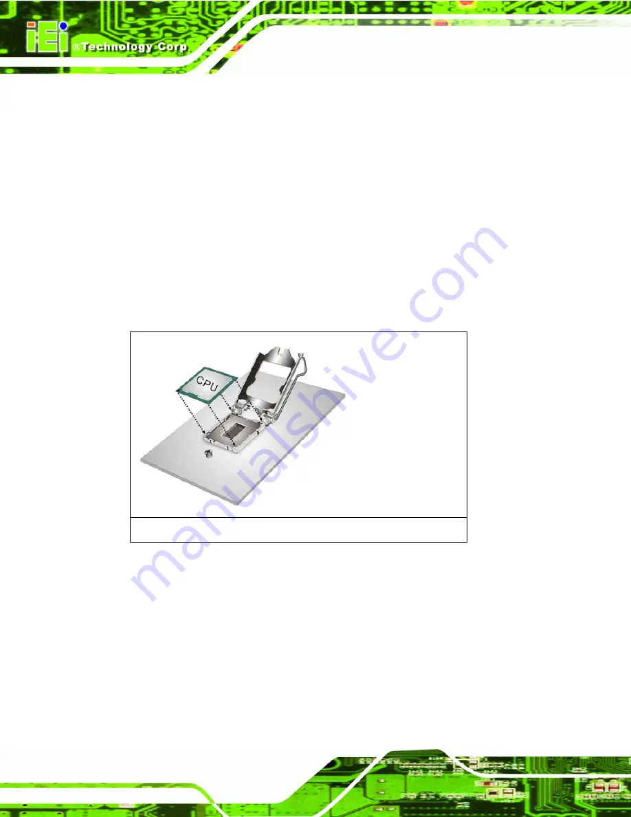
Step 7:
Insert the CPU.
Gently insert the CPU into the socket. If the CPU pins are
properly aligned, the CPU should slide into the CPU socket smoothly. See
Figure 4-3.
Figure 4-3: Insert the Socket LGA1155 CPU
Step 8:
Close the CPU socket.
Close the load plate and pull the load back a little to
have the load plate be able to secure to the knob. Engage the load lever by
pushing it back to its original position. See
Figure 4-4.
There will be some
resistance, but will not require extreme pressure.
Summary of Contents for KINO-DH610
Page 2: ...KINO DH610 Page II Revision Date Version Changes 30 December 2011 1 00 Initial release...
Page 13: ...KINO DH610 Page 1 1 Introduction Chapter 1...
Page 15: ...KINO DH610 Page 3 Figure 1 2 Connectors...
Page 21: ...KINO DH610 Page 9 2 Unpacking Chapter 2...
Page 26: ...KINO DH610 Page 14 3 Connectors Chapter 3...
Page 51: ...KINO DH610 Page 39 4 Installation Chapter 4...
Page 72: ...KINO DH610 Page 60 5 BIOS Screens Chapter 5...
Page 106: ...KINO DH610 Page 94 6 Software Drivers Chapter 6...
Page 119: ...KINO DH610 Page 107 Figure 6 20 Audio Driver Installation Complete...
Page 120: ...KINO DH610 Page 108 Appendix A A BIOS Menu Options...
Page 123: ...KINO DH610 Page 111 Appendix B B One Key Recovery...
Page 131: ...KINO DH610 Page 119 Figure B 5 Partition Creation Commands...
Page 151: ...KINO DH610 Page 139 Appendix C C Terminology...
Page 156: ...KINO DH610 Page 144 Appendix D D Watchdog Timer...
Page 159: ...KINO DH610 Page 147 Appendix E E Hazardous Materials Disclosure...


