


(C) IDM ENERGIESYSTEME GMBH
Installation instructions Hygienik 2.0
47
The following systems are just
a few examples for a much
greater range of confi guration
options for heat pump systems.
Design and planning of a sys-
tem that meets your specifi c
requirements must always be
carried out together with a sys-
tem planning engineer trained
by iDM!
Ins
tall
a
tio
n l
a
you
ts
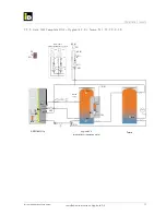
7. Installation layouts
7.1. Explanation of symbols and notes on
the installation layouts
Legend and notes on the installation layouts
Solutions from iDM are designed to offer the broadest
possible range of applications for heat pumps. Both
innovation through diversity and the use of already ex-
isting heat generation systems are key considerations.
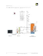
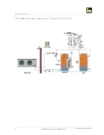
The following installation layouts are suggested con-
fi gurations. They are schematic diagrams and do not
show the full range of components required.
When actually designing a system, the specifi c con-
ditions, applicable standards and laws and the data
and information in the installation instructions must be
taken into account.
Symbol
Meaning
Heat distribution system (low-temperature heating)
Circulation pump
3-way mixing valve (without bypass), motor drive
3-way mixing valve, thermal activation
Back-pressure valve
Ball valve
Flow regulation valve
Flow switch
Safety valve
Heating manometer
Diaphragm expansion vessel
Temperature sensor
Flow sensor
Tank sensor
External sensor
Offset roomstat for heating circuit A
Offset roomstat for heating circuit C
Room thermostat
Control thermostat
Air separator
Sludge separator
Flow meter
Throttle valve
Filter
Flow sensor
Electric heating immerser
T
FS
T
TS
T
Abbreviations
HC
Heating circuit
CW
Cold water
HW
Hot water
LSP
Layer separate plate
FM
Flow meter
Pool
Swimming pool
M
T
AF
RG (A)
RG
(C)
FIL


