P
P
a
a
g
g
e
e
3
3
2
2
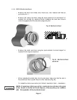
Fig 17 Aligning the missing splines.
-
Assemble the rotors (41), rotor retainers (35) and O-rings (34) onto the
shafts (9 and 10).
-
To achieve the correct timing clearance, rotate one shaft, whilst securing
the other. The gear (14) will rotate on the lubricated O-rings until the
correct mesh clearance is achieved. For mesh, clearances refer to
section 5.1.
-
If the rotor clearances cannot be achieved, then the rotor assembly will
need to be dismantled and the shaft assembly removed from the
gearbox. Rotate one tooth on the gear mesh, replace the shaft, and re-
adjust the timing once more.
-
Once the correct clearances have been achieved, tighten the gear
retaining screw (23) to the correct torque see section 5.2, and mark the
teeth at the mesh point, see Fig 18.
-
Recheck all clearances before moving on to the next stage.
Summary of Contents for Wright Flow Technologies RTP Series
Page 1: ...P Pa ag ge e 0 0 INSTALLATION OPERATION AND MAINTENANCE MANUAL FOR THE RANGE OF PUMPS...
Page 47: ...P Pa ag ge e 4 46 6 5 0 Specifications 5 1 Clearance Chart B A C Radial D C Radial...
Page 54: ...P Pa ag ge e 5 53 3 5 6 Typical Basic Pump Build RTP20 Shown...
Page 56: ...P Pa ag ge e 5 55 5 5 8 RTPTM Service History Pump Serial No Date Comments...

