9
Harrier GTE -
Installation & Servicing
GENERAL
7
2
15
16
10
14
13
7
24
23
7
12
1
7
21
7
13
22
8
7
10
27
7 26
25 7
10
9
11
3
6 7
6
18
20
7
19
13
7
17
4
5
7
7
7
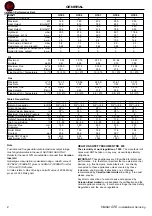
Note.
Minimum static head
requirements with limit thermostat
set at 110ºC (230ºF) is 2.5m.
The example illustrated is intended
as a general guide only. Caradon
Ideal Limited will be pleased to
advise on specific applications.
Design and minimum flow rate
tables are shown Frame 8.
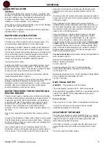
System Design
Recommendations relating to water system design are
contained in BS. 5410: Part 2 and BS. 6880.
System design must allow for adequate internal circulation
within the boiler and sufficient heat release from the boiler
body during and immediately after burner firing. Heating and/
or hot water controls should be interlocked electrically with the
burner, to prevent firing when the system does not demand
heat.
Depending on system design it may be necessary to interrupt
electrical supply to the burner before any mixing valves are
completely closed to the boiler flow. This will dissipate residual
heat. Also a pump overrun of at least 5 minutes is required on
plant shutdown to avoid interference trip out of the overheat
thermostat. If system return temperature remains below 30ºC
for most of the heating period some protection from
condensation is required.
Please contact Caradon Ideal Limited for further information.
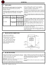
LEGEND
1. Heating outlet
2. Heating return
3. 3 bar safety valve and pressure gauge
4. Flow switch (if necessary)
5. Air separator
6. Automatic venting valve
7. Valve
8. Shunt pump (required for all models)
9. Expansion tank
10. Draining valve
11. Sludge valve
12. Mixing valve
13. Non return valve
14. Heating pump
15. Low-water safety pressure-sensitive switch
16. Sludge decanting pot (particularly recommended for
older heating systems)
17. Independent calorifier
18. Sealed safety unit calibrated to 7 bar with indicator type
discharger
19. Pressure reducer (if mains press >5.5 bar)
20. Domestic cold water inlet
21. Domestic hot water outlet
22. DHW pump
23. DHW circulation pump (optional)
24. DHW circulation loop return
25. Water meter (if any)
26. Water treatment for hard water
27. Heating circuit filling (with disconnecter if required under
applicable regulations).
9
SYSTEM DESIGN CONTINUED
Example of Installation
The example below does not cover all the possible cases of
use. It is only aimed at drawing attention to the basic rules
which must be complied with. In all events, comply with
applicable codes of practice and national or local regulations.
Example shows a sealed system with domestic hot water
production via independent calorifiers.
Typical Sealed System Example
A shunt pump sized on the minimum flow rate required MUST
be fitted. Provided adequate heat dissipation can be achieved
at all times the shunt and DHW primary pumps only may run
on during the overrun period allowing the heating pump to be
switched off. This example assumes the DHW primary pump
flow rate required is less than that required for the shunt pump.

