


7
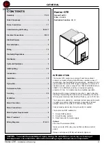
Harrier GTE -
Installation & Servicing
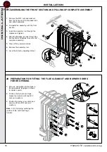
GENERAL
3
VENTILATION
Safe, efficient and trouble-free operation of conventionally
flued gas boilers is vitally dependent on the provision of an
adequate supply of fresh air to the room in which the
appliance is installed.
Ventilation by grilles communicating directly with the outside
air is required at both high and low levels. The minimum free
areas of these grilles must be according to the following
scale:
5
FILLING THE SYSTEM
Total input rating of
boilers
Position of air
vents
Air vent areas (air
direct from outside)
Up to 2 MW
HIGH LEVEL
270 cm
2
plus
2.25cm
2
per kW in
excess of 60 kW
total rated input
540 cm
2
plus
4.5cm
2
per kW in
excess of 60 kW
total rated input
LOW LEVEL
Position ventilation grilles to avoid the risk of accidental
obstruction by blockage or flooding. If further guidance on
ventilation is required then consult BS 6644.
The supply of air by mechanical means to a space housing the
boiler should be by mechanical inlet with natural or mechanical
extraction. Mechanical extract ventilation with natural inlet must
not be used.
Where a mechanical inlet and a mechanical extract system is
applied, the design ventilation flow rates should be as in Table 4
of BS 6644.
Note.
For mechanical ventilation systems an automatic control should
be provided to cause safety shutdown or lockout of the boiler(s)
in the event of failure of air flow in either inlet or extract fans.
IMPORTANT. The use of an extractor fan in the same room as
the boiler (or in an adjacent communicating room) can, in
certain conditions, adversely affect the safe operation of the
boiler.
Where such a fan is already fitted (or if it is intended to fit an
extractor fan after installation of the appliance) the advice of the
gas supplier should be obtained.
The temperature within a boiler room shall not exceed 25ºC
within 100 mm of the floor, 32ºC at mid height and 40ºC within
100 mm of the ceiling.
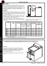
Filling shall be performed with a low flow rate from a low point
in the boiler room in order to ensure that all the air in the boiler
is bled from the high point of the system.
Always stop the pump before filling.
IMPORTANT. Instructions for starting up the boiler for the first
time after the system is fully or partly drained:
If all the air is not bled naturally to an expansion tank which is
open vented, the system must include manual bleed valves, in
addition to automatic air vents which bleed the system when it is
operating. The manual bleed valves are used to bleed all the
high points of the system and to make sure that the filled system
is free of air before the burner is turned on.
General
Recommendations relating to the water system are contained in
BS. 6880.
4
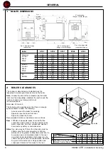
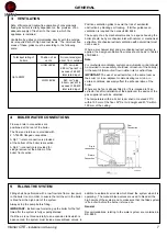
BOILER WATER CONNECTIONS
Flow and return connections are
positioned at the rear of the boiler.
The flow and returns are provided with
2
1
/
2
"/65DN flanged connections.
A Rp 1
1
/
2
drain connection is provided
at the bottom of the boiler rear section.
A Rp 2
1
/
2
connection is provided for
sludge removal at the bottom of the
boiler front section.
105
8
27
1017
137
har5965
Flow
Connection
Return
Connection
Drain
Connection
1
1
5


