22
Falcon GTE -
Installation & Servicing
INSTALLATION
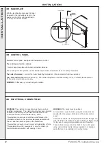
38 NAMEPLATE
WARNING.
The electrical connections must be made by a
qualified professional. The electrical wiring has been carefully
checked in the factory and the internal connections of the
control panel must not be modified in any event.
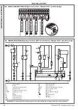
The electrical connections should be made following the
information shown on the electrical diagrams delivered with
the unit and the directions given in the instructions.
The electrical connection must comply with standards in force.
The equipment must be powered by a circuit containing a
remote double-pole switch with opening
≥
3mm.
Affix the identification plate and CE label
(supplied in the instructions bag) on the
casing (on the left or right-hand side) in
an easily accessible location.
F 67110 NIEDERBRONN
Type of boiler
Unit serial no.
Year (1)
X X - X X
Week
Date of manufacture
FAL5851
39 CONTROL PANEL
Electrical control panel, equipped with temperature control.
The control panel carton contains:
1 control panel complete with burner connection harness.
The control panel incorporates a boiler thermostat controller, a thermometer and a safety thermostat.
The boiler thermostat
- controls the boiler operating temperature. (May incorporate high/low operation)
The safety thermostat
(with manual reset) - if the boiler temperature rises abnormally (110
o
C), the safety thermostat cuts
off the burner electricity power supply.
WARNING
. In this case, you must call your installer.
WARNING
. The boiler must be earthed.
All connections must be made using the terminal blocks
provided for this purpose at the back of the boiler control
panel.
Connections cables are brought inside the boiler through cut-
outs provided in the boiler back panel, which are large enough
for the use of commercially available conduit if required.
These cables are secured at the back of the control panel
using cable clamps (cable clamps supplied in a separate
pack) that are to be installed on the sheet metal.
40 ELECTRICAL CONNECTIONS
INST
ALLA
TION

