14
Mexico Super RS 3/60P - 3/100P -
Installation
INSTALLATION
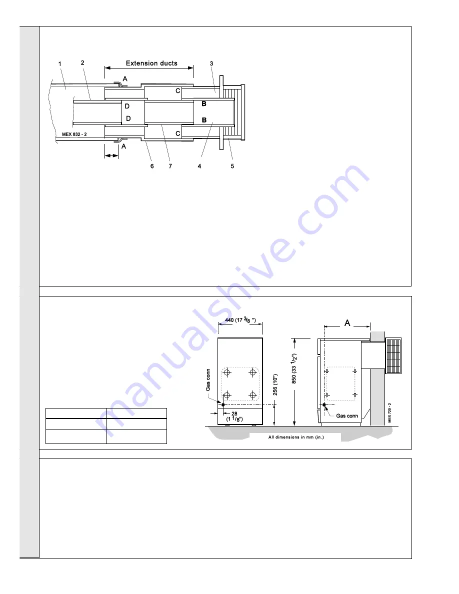
10 EXTENSION DUCTS
-
Duct lengths greater than 400 mm (16")
Extension ducts shown fitted
provided, at join (A). Ensure that a good seal is
made, particularly at the 2 bottom corners where
the boiler duct is flanged .
3.
Remove the terminal assembly.
4.
Place the boiler in position, entering the
extension duct into the wall opening.
5.
Make good the brickwork around the air duct
inside.
6.
Separate the terminal grille, terminal air duct and
terminal flue duct. Refer to Frame 8 or 9.
7.
From OUTSIDE of the building, pass the terminal
air duct through the wall opening and slide it into
the extension air duct, locating it as shown.
8.
Push the duct fully in until the fixing brackets
contact the wall face.
9.
Ensure that the duct is level and make good
between the wall and the duct from OUTSIDE of
the building.
10.
From OUTSIDE of the building, seal the duct join
(C) with the mastic provided
11.
From OUTSIDE of the building, slide the
extension flue duct into the boiler flue duct to the
same distance as the extension air duct. Seal the
duct join (D) with the mastic provided
12. RS 3/60P
Go to Frame 8 note. 7
RS 3/75P & 3/100P
Go to Frame 9 note. 6
Typical minimum
overlap - 50mm (2")
Legend
1.
Boiler air duct
2.
Boiler flue duct
3.
Terminal air duct
4.
Terminal flue duct
5.
Terminal grille
A.
Air duct join
B.
Flue duct join
C.
Terminal air
duct join
D.
Terminal flue
duct join
6.
Extension air duct
7.
Extension flue
duct
1.
BEFORE PLACING THE BOILER IN POSITION, loosely fit the
extension air duct and terminal assembly to the boiler air duct and
adjust to the required overall duct length.
Note.
Ensure that any of the duct overlaps are not less than 50 mm (2").
2.
Secure the extension air duct in position, using the adhesive tape
2.
Ensure that all valves are open. Fill and vent the system
and check for water soundness.
Notes.
a.
Isolating valves must be fitted as close to the pump as
possible.
b.
The boiler is not suitable for use with a direct hot water
cylinder or a sealed system.
12 WATER CONNECTIONS
1.
Connect the system flow and return pipework to the boiler
as appropriate. Refer to Frames 13 and 14 for guidance
on system design.
Note.
When the required output exceeds 14.4 kW (49 000
Btu/h) then 28mm (1") pumped flow and return pipes
should be used, both to and from the boiler.
Gravity connections MUST be at least 28mm (1").
11 GAS CONNECTION
1.
A MINIMUM working gas pressure of 37 mbar
(14.8 in.w.g.) MUST be available at the boiler
inlet, with the boiler operating.
2.
Extend a gas supply pipe NOT LESS THAN
15mm (
1/2
") OD to the boiler and connect to
the gas cock situated at the front LH side of
the boiler.
3.
Test the gas installation for soundness and
purge in accordance with BS.6891: 1988.
Refer to Frame 24.
Boiler
Dimension A
RS 3/60P & RS 75P
400 (15
3/4
")
RS 3/100P
473 (10
5/8
")
INST
ALLA
TION


