


6
4) Once the current has stabilized, a reading should be
taken and the anticipator adjusted to that value. If
longer heating cycles are desired, the anticipator can
be set to a higher value
2.5.2.
Ducts and filters
The ducts must be sized such a way as to accommodate the
specified airflow and the available static pressure. Refer to the
applicable local and/or national installation codes.
Insulate the ducts that lead through non-heated areas. Use
flexible supply and return air connectors to avoid the
transmission of vibration. To make the unit run even quieter,
the installer should:
1) Use two elbows between each outlet and the supply
and return air plenum;
2) Cover the vertical sections of the supply and return air
duct with soundproofing material;
3) Use baffles in short radius elbows;
4) Use flexible hangers to suspend the ducts.
The
SUPREME
furnace is equipped with a filter frame for the
blower compartment. It must be installed on the outside of one
of the three sides or the bottom of the furnace. Once the
location of the installation has been determined, use the four
square knockouts for ease of cutting the opening.
A heat pump or an air conditioner can be added to this furnace,
in either the supply or return air duct. Carefully follow the
instructions provided with these appliances to ensure proper
installation and hook-up to the electric furnace. Refrigerant and
drainage pipes must in no way hinder access to the furnace
panels.
2.6
SUPPLY AIR ADJUSTMENTS
On units equipped with 4-speed blower motors, the supply air
must be adjusted based on heating/air conditioning output and
the static pressure of the duct system. For the desired airflow,
refer to the following table as well as the airflow tables based on
static pressure in the Technical Specifications section of this
manual.
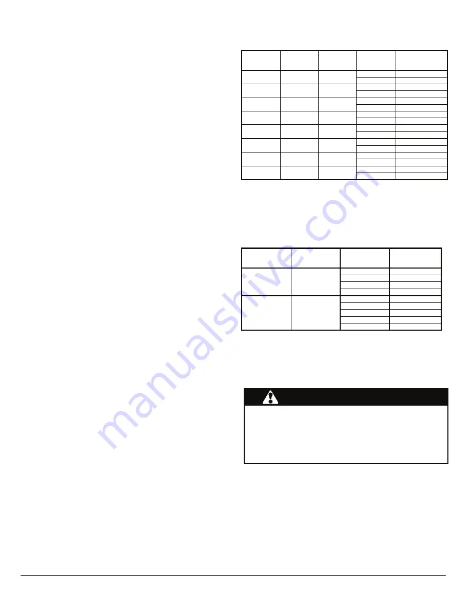
For the adjustment of the airflow on heating mode, to obtain the
temperature rise described in the technical specification table on
p.10, the orange wire must be positioned on the terminal
corresponding to the LOW, MED-LOW, MED-HIGH or HIGH
blower speed. Blower speed are adjusted in factory for 0.5 inch
static pressure.
Supply air adjustment on heating mode
FURNACE
INPUT
POWER
KW
HP MOTOR
STATIC
PRESSURE
(in. w.c)
RECOMMENDED
BLOWER SPEED
0.2
LOW
FEM10
10
1/3
0.5
LOW
0.2
MED-LOW
FEM15
15
1/3
0.5
MED-LOW
0.2
MED-LOW
FEM18
18
1/3
0.5
MED-LOW
0.2
MED-LOW
FEM20
20
1/3
0.5
MED-HIGH
0.2
MED-HIGH
FEM23
23
1/3
0.5
MED-HIGH
0.2
MED-LOW
FEM20
20
1.0
0.5
MED-LOW
0.2
MED-LOW
FEM23
23
1.0
0.5
MED-LOW
0.2
MED-LOW
FEM27
27
1.0
0.5
MED-LOW
For the adjustment of the airflow on air-cooling mode, to obtain
a sufficient airflow (350 to 450 CFM per ton), the blue wire must
be positioned on the terminal corresponding to the LOW, MED-
LOW, MED-HIGH or HIGH blower speed. Blower speeds are
adjusted in factory for 0.5 inch static pressure.
Supply air adjustment on air cooling mode
FURNACE
HP MOTOR
COOLING
CAPACITY
(0.5” w.c.)
RECOMMENDED
BLOWER SPEED
1.5
LOW
2.0
MED-LOW
2.5
MED-HIGH
FEM10, 15, 18,
20 and 23
1/3
3.0
HIGH
2.5
LOW
3.0
MED-LOW
3.5
MED-HIGH
4.0
HIGH
FEM20, 23 and
27
1.0
5.0
HIGH
If the heating and air-cooling speed are the same, the orange
wire and the blue wire can be connected on the same terminal
on the motor.
2.7
INSTALLATION OF ACCESSORIES
WARNING
Electrical shock hazard.
Turn OFF electrical power at the fuse box or service panel
before making any electrical connections and ensure a
proper ground connection is made before connecting line
voltage.
Failure to do so can result in death or bodily injury.
Summary of Contents for SUPREME FEM10-M2401AM-A
Page 12: ...12 FIGURE 6 Wiring Diagram 10 kW with 1 3 HP motor...
Page 13: ...13 FIGURE 7 Wiring Diagram 15 kW with 1 3 HP motor...
Page 14: ...14 FIGURE 8 Wiring Diagram 18 and 20 kW with 1 3 HP motor and 20 kW with 1 0 HP...
Page 15: ...15 FIGURE 9 Wiring Diagram 23 kW with 1 3 HP and 1 HP motor...
Page 16: ...16 FIGURE 10 Wiring Diagram 27 kW with 1 HP motor...
Page 17: ...COMPONENTS AND REMPLACEMENT PARTS 17...
Page 18: ...18 PARTS LIST Exploded View B50002F Please refer to Table 4 p 20...


