


Ethernet I/O Modules
ICP DAS CO., LTD.
PETL/tET/tPET DIO Series User Manual, Ver. 2.2, Aug. 2017, Page: 78
Step 3: Configure the I/O Pair connection on the tPET-P2POR2 #1 module
1.
In the eSearch Utility, select
tPET-P2POR2 #1 module
and then click the “
Web
” button to launch
the browser program and connect to the web server.
2.
Enter the password in the Login password field
(the default password is “Admin”)
, and then click
the
“Submit”
button to display the configuration page.
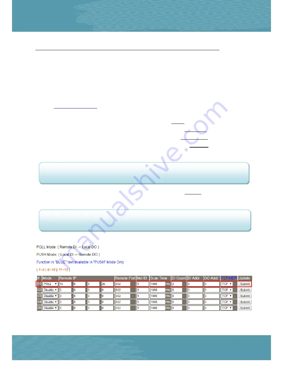
3.
Click the
“Pair
” tab to display the I/O Pair-connection Settings page.
Refer to
Figures 5-1.3
to
5-1.4
for illustrations of how to perform the above procedure.
4. In the “I/O Pair-connection Settings”, select
“POLL”
from the “
Mode
” drop-down options.
5. Enter the
IP address for remote slave device (e.g., ET-2260)
in the “
Remote IP
” field.
6. Enter the
TCP Port for remote slave device (e.g., ET-2260)
in the “
Remote Port
” field.
7. Enter a
DI Count Value for remote slave device (e.g., ET-2260)
in the “
DI Count
” field (Remote DI to
Local DO).
For example, enter
“2”
in the
“DI Count”
field. This means
DI x2 of the ET-2260 module
is mapped
to
DO x2 of tPET-P2POR2 #1 module
.
8. Enter the
DI address for remote slave device (e.g., ET-2260)
in the “
DI Addr
” field (Remote DI to
Local DO).
For example, enter
“0”
in the
“DI Addr”
field. This means
DI addresses DI0 and DI1 of the ET-2260
module
are mapped to
DO x2 of tPET-P2POR2 #1 module
.
Figure 5-3.3


