background image

5

ABOUT THE SETTING SCREEN

5-7

3. [Information] Menu

[Information]–[SYSLOG]

M

 SYSLOG

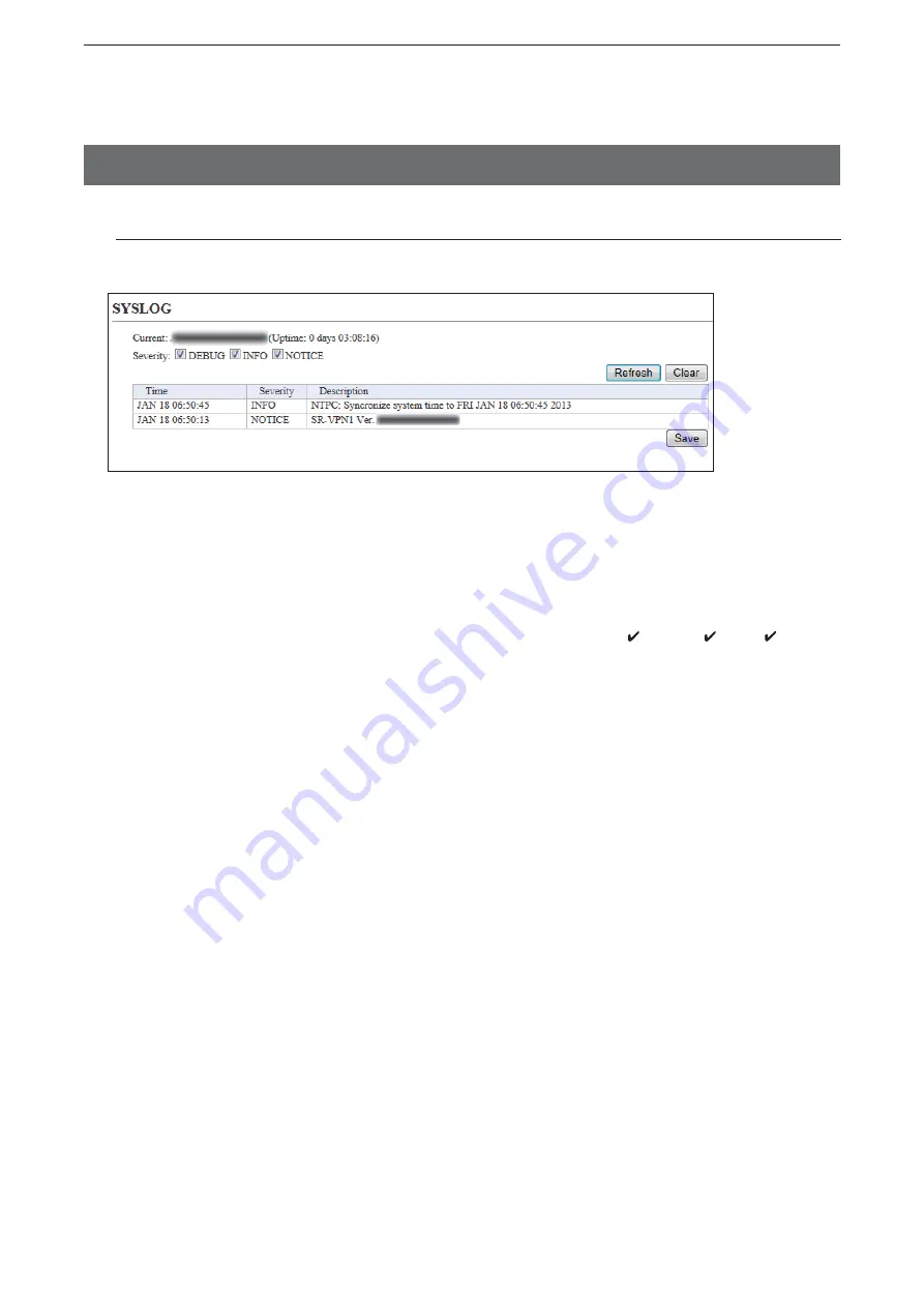
Displays the log information. The latest 500 log entries are displayed.

(This is an example.)

q

 Severity ……………………


Select the log information to display.
•  Enter a check mark to display the log entries.
•  Remove the check mark and click <Refresh> to hide the entries.
  

(Default: 

M

 DEBUG  

M

 INFO  

M

 NOTICE)

Note:  The selection is not stored, and reset when you leave this screen.

w


<Refresh> …………………


Click to refresh the log screen.

e


<Clear> ……………………


Click to delete all log entries.
Note:  All log entries are also deleted when the SR-VPN1 is turned OFF or 

initialized.

r


<Save> ……………………


Click to save the log to a PC with a text file (extension: “txt”).
• Click this button, and then select a folder to save the file.

K

q

K

w

K

e

K

r

Summary of Contents for SR-VPN1

Page 1: ...UCTION MANUAL SR VPN1 VPN ROUTER INTRODUCTION 1 BEFORE USING THE SR VPN1 2 ABOUT THE INTERNET CONNECTION 3 IPsec Wizard 4 OTHER BASIC FUNCTIONS 5 ABOUT THE SETTING SCREEN 6 MAINTENANCE 7 FOR YOUR INFORMATION ...

Page 2: ...duced or transmitted in any form or by any means electronic or mechanical including photocopying recording or by any information storage and retrieval system without express written permission from Icom Incorporated All stated specifications and design are subject to change without notice or obligation Adobe and Reader are registered trademarks of Adobe Systems Incorporated in the United States an...

Page 3: ...r fail safe configuration maintains VPN connection if either of the two network connection is working Notes This function is disabled as the default When the same network address is assigned to the WAN1 Main line and WAN2 Sub line this function doesn t properly work Icom is not responsible for any result of using this function Supports SNMP Access restriction with the IP Filter function Automatic ...

Page 4: ...th lower and upper case As of February 2013 Menu Screen Item Item name Value Network Settings IP Address IP Address IP Address 192 168 0 1 Subnet Mask 255 255 255 0 DHCP Server DHCP Server DHCP Server Enable Router Settings WAN1 WAN2 Connection Type Connection Type None WAN Failover WAN Failover WAN1 Failure Detection Disable Management Administrator Administrator Username admin fixed Current Pass...

Page 5: ... Step 3 Step 4 Step 5 Connect to a PC and turn ON the power CONNECTION GUIDE Separated Access the setting screen CONNECTION GUIDE Separated Section 1 Configure the network connection Section 2 Configure the internet connection Section 3 Configure the VPN connection using the IPsec Wizard Section 4 ...

Page 6: ...en P5 5 In the following cases you need to know the MAC addresses When cloning the SR VPN1s settings using a USB flash drive you need to create folders whose names are each SR VPN1 s LAN MAC address P6 11 When your ISP requires you to register the MAC address v 0090C7 0090C7 0090C7 WAN MAC addresses LAN MAC address This is an example Serial label SR VPN1 ...

Page 7: ...1 1 BEFORE USING THE SR VPN1 Section 1 1 Panel description 1 2 M Front panel 1 2 M Rear panel 1 4 2 Feature description 1 5 M About the Routing function 1 5 M About the VPN function 1 6 ...

Page 8: ... Green and Orange LEDs alternately light Firmware update is in progress e MSG Lights green A firmware update is ready Blinks green Downloading new firmware Lights orange Accessing the USB flash drive r WAN 1 2 Doesn t light Not connected 1000BASE T connection Lights green Connected to the WAN Blinks green The WAN line is communicating 10BASE T 100BASE TX connection Lights orange Connected to the W...

Page 9: ...e SR VPN1 s power before inserting or removing the USB flash drive to prevent data corruption Either one of the USB slots accepts the USB flash drive but insert only one USB flash drive at a time Insert the USB flash drive securely NEVER remove the USB flash drive or turn OFF the SR VPN1 s power while transferring data It will cause data corruption or damage the USB flash drive After the firmware ...

Page 10: ... w e WAN ports The Routing function is disabled as the default Connect the modem ADSL VDSL CATV or ONU Optical Network Unit to the WAN1 port and then select the network line type DHCP client PPPoE Static IP as specified by your internet service provider ISP P2 3 The WAN2 port can be used as the backup line P2 9 r INIT button If you cannot access the setting screen push this button to initialize th...

Page 11: ...ic IP as specified by your ISP The WAN2 port can be used as the backup line P2 9 Connecting a Router modem Connect the router modem to the WAN1 port Select the network line type DHCP client PPPoE Static IP as specified by your ISP The WAN2 port can be used as the backup line P2 9 ISP WAN1 LAN1 LAN2 SR VPN1 INTERNET INTERNET Bridge modem DCE FTTH ISP WAN1 LAN1 LAN2 Router modem SR VPN1 INTERNET INT...

Page 12: ...ublic net works like the Internet as if it were a private network You can easily configure the VPN connection using the IPsec Wizard P3 1 Connect the WAN line to the WAN port and then configure the Router function to use the VPN function P3 3 You can perform further settings on the IPsec or IPsec Setting Details screen P5 51 to P5 65 SR VPN1 SR VPN1 IPsec based VPN INTERNET INTERNET ...

Page 13: ...cting the internet connection method 2 3 Step 4 Connecting the modem 2 3 Step 5 Select the network line type 2 4 M When the IP address is obtained by DHCP 2 4 M When using a static IP address 2 5 M When the IP address is obtained in the PPPoE method 2 7 Information About the WAN Failover function 2 9 M About the problem detecting method 2 9 ...

Page 14: ... network connection method Connecting a Bridge modem Connect a Bridge modem or DCE FTTH to the WAN1 port The WAN2 port can be used as a backup line P2 9 Connecting a Router modem Connect a Router modem to the WAN1 port The WAN2 port can be used as a backup line P2 9 ISP WAN1 LAN1 LAN2 SR VPN1 INTERNET INTERNET Bridge modem Terminal unit TU ISP WAN1 LAN1 LAN2 Router modem SR VPN1 INTERNET INTERNET ...

Page 15: ...s automatically obtained by a DHCP server Using a static IP address P2 5 The WAN IP address is specified by your ISP The IP address is obtained in the PPPoE method P2 7 The WAN IP address is specified by your ISP in the PPPoE method When using a Router mode When the router modem s LAN IP address is the same as that of the SR VPN1 you need to change the SR VPN1 s LAN IP address default 192 168 0 1 ...

Page 16: ...eboot When you are asked to reboot the SR VPN1 follow the instructions 4 Select the network line type Step 5 Select the network line type MWhen the IP address is obtained by DHCP After rebooting verify that Connecting appears in the Connection Status item Click Refresh to update the screen 5 Click If Connected doesn t appear verify the setting Select Click Verify ...

Page 17: ...IP address Step 5 Select the network line type continued Click Router Settings then WAN1 The WAN1 screen appears 1 Select Static IP in the Connection Type item Enter the values into the items in the Connection Settings field as specified by your ISP 2 3 Click Apply 4 Select Enter Click ...

Page 18: ...ect the network line type continued Click Reboot When you are asked to reboot the SR VPN1 follow the instructions 5 After rebooting verify that Connecting appears in the Connection Status item Click Refresh to update the screen 6 If Connected doesn t appear verify the setting Click Verify ...

Page 19: ...s 1 Select PPPoE in the Connection Type item Select or enter the value into the items in the Connection Settings field 2 3 Click Apply 4 MWhen the IP address is obtained in the PPPoE method Step 5 Select the network line type continued Continued on the next page Select Select or Enter Click ...

Page 20: ...E connections is established 6 Click Refresh to update the screen 7 MWhen the IP address is obtained in the PPPoE method continued Step 5 Select the network line type continued Click Reboot When you are asked to reboot the SR VPN1 follow the instructions 5 Note If Connected doesn t appear check the entries set in Step 3 Click qSelect wClick qClick wVerify ...

Page 21: ... item depending on your network environment 5 31 Disable Don t use the WAN Failover function LINK Status Detects the failure by the link status The detecting method differs depending on the connection type DHCP Client The IP address has not been obtained Static IP Connectivity of the WAN1 port PPPoE Connectivity of the PPPoE line DNS Lookup Detects the failure by the query response from the DNS se...

Page 22: ...3 1 IPsec Wizard Section 3 Step 1 About the network connection type 3 2 Step 2 About the setting items 3 3 Step 3 Configure the IPsec tunnel 3 4 ...

Page 23: ... ID keyid_icom KEYID Static IP IP Network WAN IP Address 192 168 100 2 static Static IP LAN Subnet 192 168 1 0 24 IP Network WAN IP Address 192 168 100 2 static LAN Subnet 192 168 1 0 24 Dynamic IP ID keyid_icom KEYID IP Network WAN IP Address Dynamic IP LAN Subnet 192 168 1 0 24 Host XXXXXXXXXX jp Dynamic IP ID keyid_local KEYID Peer s ID keyid_remote KEYID Dynamic DNS server Static IP to Dynamic...

Page 24: ...28 characters The ID of the other SR VPN1 Site B Static IP Dynamic IP Dynamic IP Dynamic IP Type KEYID FQDN USER FQDN String Up to 128 characters 1 Optional 2 When the dynamic WAN IP addresses are assigned to both SR VPN1s enter the host name of the other SR VPN1 Site B One or the other SR VPN1 needs to be registered to the dynamic DNS server and obtain the host name If the SR VPN1 Site A has been...

Page 25: ...3 for the details NOTE Before configuring the IPsec tunnel configure the Router function for the WAN in the Router Settings menu You can use this wizard to configure the basic operation of the IPsec tunnel You can also perform further settings on the IPsec or IPsec Setting Details screen P5 51 to P5 65 Up to 32 IPsec tunnels can be created Static IP to Static IP connection SR VPN1 SR VPN1 Peer IP ...

Page 26: ...lick Back if you want to change the entry 4 5 Step 3 Configure the IPsec tunnel continued If you want to create another tunnel click Back to Top You can monitor the status of tunnels on the IPsec or IPsec Setting Details screen P5 51 to P5 65 This is an example qEnter qConfirm Click wClick wClick ...

Page 27: ...4 Setting example 4 4 About the DHCP server function The SR VPN1 s DHCP server function is enabled as the default Before connecting the SR VPN1 to a network make sure that the addresses of the devices on the network don t over lap or conflict If a DHCP server is already connected to the network and there is an address conflict a network problem will occur See the Troubleshooting section for possib...

Page 28: ...ord and change it occasionally Choose one that is not easy to guess Use numbers characters and letters both lower and upper case Click the Management menu then Administrator The Administrator screen appears 1 Enter Current Password New Password and New Password confirm in their respective input fields The password can be composed of up to 31 characters 0 9 a z and A Z The entered characters are di...

Page 29: ...rent time is displayed in Date and Time Click Apply to synchronize the internal clock with the current time You can also enter the time in the Manually Set Time item 2 Setting date and time Manual setting Setting date and time Automatic setting The Automatic Clock Synchronize function automatically synchronizes the internal clock with the time management server NTP To use this function an internet...

Page 30: ...ons 3 About the DHCP server function The SR VPN1 s DHCP server function is enabled as the default Before connecting the SR VPN1 to a network make sure that the addresses of the devices on the network don t over lap or conflict If a DHCP server is already connected to the network and there is an address conflict a network problem will occur See the Troubleshooting section for possible solutions Abo...

Page 31: ...e 5 11 M Traffic Statistics 5 12 4 Network Settings Menu 5 14 M Host Name 5 14 M IP Address 5 15 M DHCP Server 5 16 M Static DHCP 5 18 M Static DHCP Table 5 18 M Routing Table 5 19 M Static Routing 5 20 M List of Static Routing Entries 5 20 About the connection type Some items differ depending on the connection type selected in the Connection Type item DHCP Client appears when DHCP Client is selec...

Page 32: ...ist of Connection Settings 5 30 M WAN Failover 5 31 M Current Status 5 33 M NAT 5 34 M DMZ Host 5 34 M Port Forwarding 5 35 M List of Port Forwarding Entries 5 35 M IP Filter Setting 5 36 M List of IP Filter Entries 5 45 M Dynamic DNS 5 46 M Dynamic DNS Updates 5 48 6 VPN Settings Menu 5 49 M IPsec Wizard 5 49 M IPsec Common Settings 5 50 M Tunnel 5 51 M Routes 5 53 M List of IPsec Settings 5 54 M...

Page 33: ...y Management 5 75 M SSH Public Key Registration Status 5 75 M Date and Time 5 76 M Time Zone 5 77 M NTP 5 78 M SYSLOG 5 79 M SNMP 5 80 M Ping Test 5 83 M Traceroute Test 5 84 M Reboot 5 85 M Backup Settings 5 86 M Restore Settings 5 86 M List of Settings 5 87 M Factory Defaults 5 88 M Firmware Status 5 89 M Online Update 5 90 M Automatic Update 5 91 M Manual Update 5 91 ...

Page 34: ...el setting values If A reboot is required to apply all the new settings is displayed on the screen when you click the Apply button click the OK button The SR VPN1 reboots and the setting items and values are updated The following message is displayed on the screen while the SR VPN1 is rebooting If the setting screen does not automatically return click Back in about 30 seconds after the Now rebooti...

Page 35: ...us Displays the firmware version and MAC addresses WAN LAN MNetwork Status Displays the network information such as IP addresses WAN LAN The MAC addresses are also printed on the label on the bottom of the SR VPN1 TOP This is an example This is an example ...

Page 36: ... enabled and can automatically select the optimal speed and duplex mode if the peer devices are auto negotiation enabled as well We recommend to always enable auto negotiation on the peer devices If a peer device is fixed to full duplex mode auto negotiation enabled devices including the SR VPN1 may generally take it for half duplex mode and cannot com municate properly This is an example ...

Page 37: ...e the check mark and click Refresh to hide the entries Default M DEBUG M INFO M NOTICE Note The selection is not stored and reset when you leave this screen w Refresh Click to refresh the log screen e Clear Click to delete all log entries Note All log entries are also deleted when the SR VPN1 is turned OFF or initialized r Save Click to save the log to a PC with a text file extension txt Click thi...

Page 38: ...ready Constructing Connection in progress Disconnected Down Disconnected IPsec Disabled The SR VPN1 s IPsec function is disabled tRemote ID The ID of the SR VPN1 Site B in the illustration below yLocal ID The ID of the SR VPN1 Site A in the illustration below u Detail Click to open the tunnel details window P5 9 Information VPN Status K q K w K e K r K t K y K u This is an example An IPsec connect...

Page 39: ... tunnel rLocal IP Address The WAN IP address of the SR VPN1 Site A in the illustration below tLocal IP Address The WAN IP address of the SR VPN1 Site B in the illustration below Phase1 ISAKMP SA Phase2 IPsec SA yIntegrity Algorithm The authentication algorithm used for the IKE phase 1 2 uEncryption Algorithm The encryption algorithm used for the IKE phase 1 2 iDH Group The DH group used for the IK...

Page 40: ...he IPsec routing status qDestination The network address of the route s destination network wSubnet Mask The subnet mask of the route s destination network eRoute The tunnel number of the route Information VPN K q K w K e 3 Information Menu continued Information VPN Status This is an example ...

Page 41: ...nterval Select the plot interval Default 2 minutes wRefresh Automatically Select Enable to periodcally refresh the graph Default Enable The graph is refreshed according to the set interval in Plot Interval q e Open Click to open the memory usage graph window The X axis represents the date and time and the Y axis represents the usage This is an example Information Statistics K e K q K w ...

Page 42: ...k mark to hide the graph Default M mirror0 LAN M eth1 WAN1 M eth2 WAN2 wPlot Interval Select the plot interval Default 2 minutes eRefresh Automatically Select Enable to periodically refresh the graph Default Enable The graph is refreshed according to the set interval in Plot Interval w rSingle Window Select Enable to display all graphs on the same window Default Enable When Disable is selected the...

Page 43: ... MTraffic Statistics continued t Open Click to open the traffic graph window The X axis represents the date and time and the Y axis represents the usage This is an example Information Statistics K t K q K w e r In Incoming traffic Out Outgoing traffic ...

Page 44: ...Network Settings Menu MHost Name Enter the host name Host Name Enter the host name Up to 31 characters Default SR VPN1 Note The name must start with an alphanumeric character and must NOT start or end with a Network Settings IP Address ...

Page 45: ... must be the same as that set in the IP Pool Start Address item in the DHCP Server menu P5 16 wSubnet Mask Enter the subnet mask according to your network environment Default 255 255 255 0 eDefault Gateway If a default gateway device such as a router is connected to the LAN port enter the device s IP address If the default gateway is set to the LAN side the network route is on the WAN side when th...

Page 46: ...e of IP pool Default 30 Note Up to 128 addresses can be automatically assigned by the DHCP server function Another 32 addresses can be manually assigned rSubnet Mask Enter the subnet mask for the IP pool start address set in the IP Pool Start Address item w Default 255 255 255 0 tLease Time Enter the lease time period Default 72 Range 1 9999 hours yDomain Name Enter the network address domain name...

Page 47: ...eway IP address iDNS Proxy Select Enable to use the DNS Proxy function Default Enable When Enable is selected you don t need to change the DHCP clients setting even when the DNS server address has changed oPrimary WINS Server Enter the WINS server s primary address 0Secondary WINS Server Enter the WINS server s secondary address Network Settings DHCP Server ...

Page 48: ...ies Static DHCP Enter the MAC and IP addresses and then click Add Note Make sure that the addresses of the devices on the network don t overlap or conflict If a DHCP server is already connected to the network and there is an address conflict a network problem will occur See the Troubleshooting section for possible solutions Delete Click Delete to remove the entry This is an example Network Setting...

Page 49: ... of the route s destination network wSubnet Mask The subnet mask of the route s destination network eGateway The route s gateway address rInterface The routing interface lo0 Loop back interface eth1 Static IP or DHCP client WAN1 eth2 Static IP or DHCP client WAN2 pppoe0 PPPoE WAN1 pppoe1 PPPoE WAN2 mirror0 LAN tOwner The type of routing path static Static route misc Broadcast frame host Host route...

Page 50: ...List of Static Routing Entries This is an example This is an example Network Settings Static Routing K q K w K e K r qDestination The network address of the route s destination network wSubnet Mask The subnet mask of the route s destination network eGateway The route s gateway address r Add Click to add the entry Delete Click Delete to remove the entry ...

Page 51: ...rk Refresh Click to refresh the screen wConnection Type Displays the WAN connection type eDNS Server Displays the DNS server s IP address rIP Address Displays the SR VPN1 s WAN IP address tPeer IP Address Displays the gateway IP address obtained by the DHCP yUptime Displays the elapsed time the SR VPN1 has been connected to the network Click Refresh to refresh Router Settings WAN1 WAN2 K K K K K K...

Page 52: ...atus wConnection Type Displays the WAN connection type eDNS Server Displays the DNS server s IP address rIP Address Displays the SR VPN1 s WAN IP address tPeer IP Address Displays the gateway IP address which is manually set yUptime Displays the elapsed time the SR VPN1 has been connected to the network Click Refresh to refresh Router Settings WAN1 WAN2 K K K K K K q w e r t y ...

Page 53: ...r Connected eConnection Type Displays the WAN connection type rDNS Server Displays the DNS server s IP address tIP Address Displays the SR VPN1 s WAN IP address yPeer IP Address Displays the IP address specified by your service provider uUptime Displays the elapsed time the SR VPN1 has been connected to the network Click Refresh to refresh MConnection Status PPPoE Displays the WAN connection statu...

Page 54: ...on type as specified by your ISP Default No Connection No Connection Select this when the WAN port is not connected to the network DHCP Client The WAN IP address is automatically obtained by a DHCP server Static IP The WAN IP address is specified by your ISP PPPoE The WAN IP address is specified by your ISP in the PPPoE method Router Settings WAN1 WAN2 ...

Page 55: ...ction Settings DHCP Client Configure the WAN connection qNickname Enter the name of the connection Up to 31 characters wPrimary DNS Server Enter the primary DNS server address as specified by your ISP eSecondary DNS Server Enter the secondary DNS server address as specified by your ISP K K K q w e ...

Page 56: ...acters wIP Address Enter the WAN IP address as specified by your ISP eSubnet Mask Enter the subnet mask as specified by your ISP rDefault Gateway Enter the default gateway address as specified by your ISP tPrimary DNS Server Enter the primary DNS server address as specified by your ISP ySecondary DNS Server Enter the secondary DNS server address as specified by your ISP K K K K K K q w e r t y ...

Page 57: ... to 31 characters eUsername Enter a login user name or account name rPassword Enter a login password The entered characters are displayed as an asterisk or a dot tReconnect Mode Select the PPPoE connection method Default Always on Manual The PPPoE line can be manually connected or disconnected by clicking Connect or Disconnect P5 23 Always on The PPPoE line is always connected K K K K K K K K K K ...

Page 58: ...S Server Enter the primary DNS server address as specified by your ISP iSecondary DNS Server Enter the secondary DNS server address as specified by your ISP oAuthentication Protocol Enter the authentication protocol as specified by your ISP Default Automatic Select Automatic if not specified Router Settings WAN1 WAN2 K K K K K K K K K K K K q w e r t y u i o 0 1 2 ...

Page 59: ...0MSS Limit Enter the MSS limit if specified by your ISP Default 1322 Range 536 1452 Bytes 1AC Name Enter the access concentrator name if specified by your ISP 2Service Name Enter the service name if specified by your ISP Router Settings WAN1 WAN2 K K K K K K K K K K K K q w e r t y u i o 0 1 2 ...

Page 60: ...5 ABOUT THE SETTING SCREEN 5 30 5 Router Settings Menu continued MList of Connection Settings Delete Click to delete the entry Router Settings WAN1 WAN2 ...

Page 61: ...ing on the connection type DHCP Client The IP address has not been obtained Static IP Connectivity of the WAN1 port PPPoE Connectivity of the PPPoE line DNS Lookup Detects the failure of the query response from the DNS server No failure is detected while either the primary or secondary DNS server returns a query response Ping Detects the failure of the Ping response Enter the IP address to send th...

Page 62: ...imum number of retry attempts Default 4 Range 1 10 rRetry Interval Enter the retry period Default 30 Range 1 300 seconds tInitial Waiting Time Enter the waiting time before the Failover function starts to monitor the connectivity status after booting Default 60 Range 1 300 seconds Router Settings WAN Failover q w e r t ...

Page 63: ...on Status Displays the monitoring status Disabled Enabled Suspending or Enabled eDefault Gateway Displays the default gateway port LAN WAN1 or WAN2 rWAN1 Displays the WAN1 port IP address connection type and connection status Example 172 22 75 90 Static IP tWAN2 Displays the WAN2 port IP address connection type and connection status Example DHCP Client Disconnected w e r t Router Settings WAN Fail...

Page 64: ... Client Static IP or PPPoE MDMZ Host Configure the DMZ Host function The NAT function can be used when the connection type P5 24 is set to DHCP Client Static IP or PPPoE NAT Select Enable to use the NAT function Default Enable The NAT function converts the WAN global address into the private address DMZ Host IP Address Enter the DMZ host IP address Router Settings NAT ...

Page 65: ...the WAN port number Note Select Custom to set the WAN port by number wLAN IP Address Enter the private IP address eLAN Port Select Custom if you select the LAN port by the number rProtocol Select the protocol t Add Click to submit the entry Up to 32 tables can be submitted q Edit Click to edit the entry The entry contents are loaded to the Port Forwarding field above w Delete Click to remove the e...

Page 66: ...he filter setting Default Disable Select Disable in the unused filter entry 1 off appears on a disabled filter setting in the No item on the List of IP Filter Entries 5 Router Settings Menu continued Router Settings IP Filter MIP Filter Setting Configure the Packet Filtering function This function can be used when the connection type P5 24 is set to DHCP Client Static IP or PPPoE K K K K K K K K K...

Page 67: ...on Default IN In Filters the incoming packets from the WAN interfaces Out Filters the outgoing packets to the WAN interfaces tInterface Select the filtering interface Default Any Any All WAN interfaces eth1 Static IP or DHCP client WAN1 eth2 Static IP or DHCP client WAN2 pppoe0 PPPoE WAN1 pppoe1 PPPoE WAN2 5 Router Settings Menu Router Settings IP Filter MIP Filter Setting continued K K K K K K K ...

Page 68: ...destination IP Address and mask to filter The all packets to the entered IP address are filtered blocked or passed Leave this item blank to filter all packets Mask range 1 32 iProtocol Select the transport layer s protocol to filter Default Any Any Any protocols TCP Only TCP UDP Only UDP TCP UDP TCP and UDP 5 Router Settings Menu Router Settings IP Filter MIP Filter Setting continued Continued on ...

Page 69: ...the Type and Code items Range 0 255 IGMP Only IGMP Custom Specified by the protocol number Enter the upper layer protocol number into the Custom Value item Range 0 255 5 Router Settings Menu Router Settings IP Filter MIP Filter Setting continued K K K K K K K K K K K K K K q w e r t y u i o 0 1 2 3 4 ...

Page 70: ...SCREEN 5 40 oSource Port Select the source port or enter the TCP UDP source port number 5 Router Settings Menu Router Settings IP Filter MIP Filter Setting continued K K K K K K K K K K K K K K q w e r t y u i o 0 1 2 3 4 ...

Page 71: ...5 41 0Destination Port Select the destination port or enter the TCP UDP destination port number 5 Router Settings Menu Router Settings IP Filter MIP Filter Setting continued K K K K K K K K K K K K K K q w e r t y u i o 0 1 2 3 4 ...

Page 72: ...P flags The selected flags first character is displayed in List of IP Filter Entries P5 45 Example ACK and RST are selected 5 Router Settings Menu Router Settings IP Filter MIP Filter Setting continued K K K K K K K K K K K K K K q w e r t y u i o 0 1 2 3 4 ...

Page 73: ... filtered by the filtering entry and no more filtering conditions will be processed Disable Continues matching when the packet is matched to the filtering condition If the packet matches no other filtering conditions the packet is filtered by the filtering entry If the packet matches other filtering conditions the packet is filtered by the last matched filtering entry See qNo P5 36 for the filteri...

Page 74: ...n is displayed on the SYSLOG screen in the Information Menu P5 7 Note This function may affect the system performance We recommend not using this except for the testing purpose 5 Router Settings Menu Router Settings IP Filter MIP Filter Setting continued K K K K K K K K K K K K K K q w e r t y u i o 0 1 2 3 4 ...

Page 75: ...Delete Click to remove the entry About the default filtering conditions No 1 Blocks all incoming packets No 2 Passes all outgoing packets and its response packets Note The outgoing packets response packets are not blocked by the filter No 1 No 58 Passes the FTP packets No 59 64 These filtering conditions prevent the Windows applications from the remote access and leaking information caused by the ...

Page 76: ...f the change of the SR VPN1 s global IP address Default Disable eUpdate Interval Select the update interval Default 10 Range 1 99 days rDynamic DNS Server Select RFC2136 to use the RFC2136 dynamic DNS server Default None tServer URL Enter the RFC2136 dynamic DNS server s URL Up to 127 characters 5 Router Settings Menu continued Router Settings Dynamic DNS K K K K K K K K K K q w e r t y u i o 0 ...

Page 77: ... to 31characters iUsername Enter the user ID to access the dynamic DNS server Up to 31characters oPassword Enter the password to access the dynamic DNS server Up to 31characters The entered characters are displayed as an asterisk or a dot 0Connection Status Select Offline to inform the dynamic DNS server of the SR VPN1 s offline status Default Online 5 Router Settings Menu Router Settings Dynamic ...

Page 78: ...ote If an error message appears check the setting following the message eHost Address Displays the host name that is registered to the dynamic DNS server rIP Address Displays the global IP address that is registered to the dynamic DNS server t Refresh Click to refresh the screen y Update the Server Click to send the SR VPN1 s WAN IP address to the dynamic DNS server 5 Router Settings Menu continue...

Page 79: ...you to easily configure the VPN connection See Section 3 for details VPN Settings IPsec Wizard NOTE Connect the WAN line to the WAN port and then configure the Router function to use the VPN function You can perform further settings on the IPsec or IPsec Setting Details screen P5 51 to P5 65 ...

Page 80: ...resses An IPsec connection is basically impossible if one of them has a private IP address This is because the NAT Network Address Translation of the upper router of the SR VPN1 with a private IP address overwrites the port number of the IPsec packets The NAT Traversal function detects the NAT translation and maintains the IPsec connection appropriately To use this function select Enable at NAT Tr...

Page 81: ...Enter the IP address or host name of the other SR VPN1 Site B in the illustration below yRemote ID Select the ID of the other SR VPN1 Site B in the illustration below Default IP address Type KEYID FQDN USER FQDN String Up to 128 characters uLocal ID Select the ID of the SR VPN1 Site A in the illustration below Default IP address Type KEYID FQDN USER FQDN String Up to 128 characters VPN Settings IP...

Page 82: ...t the IPsec tunnel connection type Default Enable Enable Connects to the IPsec tunnel when the WAN IP address is obtained Disable Connects to the IPsec tunnel only when clicking Connect in the List of IPsec Settings item Not automatically connected VPN Settings IPsec K q K w K e K r K t K y K u K i ...

Page 83: ... other SR VPN1 Site B in the illustration below wSubnet Mask Enter the subnet mask to connect to the IPsec tunnel e Click to increase or decrease the number of routing paths You can add up to 5 routing paths for each tunnel VPN Settings IPsec K q K w This is an example K e An IPsec connection SR VPN1 SR VPN1 Peer IP Network IPsec tunnel Site A Site B 192 168 1 0 ...

Page 84: ...ready Constructing Connection in progress Disconnected Down Disconnected Disabled The tunnel is disabled IPsec Disabled The SR VPN1 s IPsec function is disabled tRemote ID The ID of the SR VPN1 Site B in the illustration below yLocal ID The ID of the SR VPN1 Site A in the illustration below VPN Settings IPsec K q K w K e K r K t K y K u K i K o This is an example An IPsec connection SR VPN1 SR VPN...

Page 85: ...d uStatus button Disconnect Down Click to disconnect Connect Up Click to connect i Edit Click to edit the entry The edited contents are loaded into the Tunnel and Routes fields o Delete Click to delete the entry VPN Settings IPsec K q K w K e K r K t K y K u K i K o This is an example ...

Page 86: ...continued MIPsec Detail Configure the IPsec tunnel details qNo Select the tunnel entry number The selected tunnel s settings are reloaded VPN Settings IPsec Detail Continued on the next page K q K o K o K w K 0 K 0 K e K 1 K 1 K 2 K 2 K r K t K y K u K i ...

Page 87: ...ponder use version 1 2 The initiator and responder use version 2 1 Initiator and 1 2 Responder If the SR VPN1 is set as the responder the IKE version is automatically selected according to the initiator s version If the SR VPN1 is set as the initiator version 1 is used 2 Initiator and 1 2 Responder If the SR VPN1 is set as the initiator version 2 is used VPN Settings IPsec Detail K q K o K o K w K...

Page 88: ...ct the IKE key exchange mode Default Automatic Automatic The exchange mode is automatically selected Main Mode A more secure exchange mode than the aggressive mode Aggressive Mode The mode normally used VPN Settings IPsec Detail K q K o K o K w K 0 K 0 K e K 1 K 1 K 2 K 2 K r K t K y K u K i ...

Page 89: ...ge 0 600 Default 10 Select 0 to disable the IKE keepalive tIKE Session Select the IKE key exchange method Default Initiator Responder The SR VPN1 waits for the key exchange from other SR VPN1s Initiator The SR VPN1 initiates the key exchange procedure VPN Settings IPsec Detail K q K o K o K w K 0 K 0 K e K 1 K 1 K 2 K 2 K r K t K y K u K i ...

Page 90: ...he INITIAL CONTACT notification message Default Enable Note Only for IKE version 1 uPFS Select Enable to use the PFS Perfect Forward Security function for a more secure SA key exchange Default Enable Note Only for IKE version 1 VPN Settings IPsec Detail K q K o K o K w K 0 K 0 K e K 1 K 1 K 2 K 2 K r K t K y K u K i ...

Page 91: ...2 Enable Create a new ISAKMP SA for IKE phase 1 Disable Update the ISAKMP SA for IKE phase 1 Phase 1 ISAKMP SA 2 IPsec SA oIntegrity Algorithm Select the integrity algorithm Default SHA 1 Note Set the same algorithm to both SR VPN1s MD5 Use MD5 Message Digest 5 128 bit SHA 1 Use SHA 1 Secure Hash Algorithm 1 160 bit VPN Settings IPsec Detail K q K o K o K w K 0 K 0 K e K 1 K 1 K 2 K 2 K r K t K y ...

Page 92: ...S Triple DES 168 bit AES CBC 128 bit Use AES CBC Advanced Encryption Standard Cipher Block Chaining 128 bit AES CBC 192 bit Use AES CBC 192 bit AES CBC 256 bit Use AES CBC 256 bit 1DH Group Select the DH Diffie Hellman group Default Group 1 768 bit Note The SR VPN1 supports Group 1 768 bit and Group 2 1024 bit VPN Settings IPsec Detail K q K o K o K w K 0 K 0 K e K 1 K 1 K 2 K 2 K r K t K y K u K ...

Page 93: ...800 seconds Phase 1 Seconds Range 300 691200 seconds kbytes Range 100 100000 kB Note If you set the lifetime by the transfer packet size enter it into the Lifetime item in the Phase 2 field in Mbytes Phase 2 Seconds Range 300 691200 seconds Mbytes Range 100 100000 MB VPN Settings IPsec Detail K q K o K o K w K 0 K 0 K e K 1 K 1 K 2 K 2 K r K t K y K u K i ...

Page 94: ...ued MAbout the IKE version The setting items differ depending on the IKE version IKE version 1 IKE version 2 IKE Mode Yes No IKE Keepalive Interval Yes Yes IKE Session Yes Yes INITIAL CONTACT Yes No PFS Yes No ISAKMP SA Reauth No Yes VPN Settings IPsec Detail ...

Page 95: ...y Constructing Connection in progress Disconnected Down Disconnected Disabled The tunnel is disabled IPsec Disabled The SR VPN1 s IPsec function is disabled tPhase 1 Displays the phase 1 ISAKMP SA settings in three lines yPhase 2 Displays the phase 2 IPsec SA settings in three lines u Edit Click to edit the entry The entry contents is loaded to the IPsec Detail field above VPN Settings IPsec Detai...

Page 96: ...nction Default Disable wMode Select the Multicast Routing function mode Default Client Client The received multicast packets are routed to the server Server The received multicast packets are routed to the all clients eServer IP Address Enter the routing destination IP address rKeepalive Interval Enter the keepalive interval Default 60 Range 30 28800 seconds VPN Settings Multicast K q K w K e K r ...

Page 97: ...5 ABOUT THE SETTING SCREEN 5 67 6 VPN Settings Menu MMulticast continued tIGMP Query Interval Enter the IGMP query interval Default 60 Range 30 28800 seconds VPN Settings Multicast K q K w K e K r K t ...

Page 98: ... the Site B s server s LAN IP address into the Server IP Address item You don t need to set the same IGMP Query Interval to the Server Client SR VPN1s Multicast configuration example Client Site A Site B Server SR VPN1 WAN WAN SR VPN1 IP Network LAN IP address 192 168 0 1 24 LAN IP address 192 168 1 1 24 Multicast device Multicast device 6 VPN Settings Menu continued VPN Settings Multicast Client ...

Page 99: ...rver connections status Connected The keepalive packet has been reached to the server and then the appropriate response packet is received by the client Disconnected The IPsec tunnel is disconnected or the server is not activated eIP Address The SR VPN1 s LAN IP address rGroup Address The multicast group addresses of the devices which are connected to the SR VPN1 s LAN port These addresses are not...

Page 100: ...ddress Displays the multicast group addresses The multicast packets are transferred to the client according to this setting eLifetime Displays the lifetime of the client s group addresses The lifetime is updated when a notice is received If the lifetime is set to 60 seconds default the actual is three times of set time 180 seconds When the lifetime is 0 second the client s group addresses are disc...

Page 101: ...rgotten the password you cannot access the SR VPN1 s setting screen again In this case you have to initialize the SR VPN1 using the INIT button See the supplied Precautions leaflet for details qUsername Displays the administrator login ID admin wCurrent Password Enter the current password when you change it Default admin The entered characters are displayed as an asterisk or a dot eNew Password En...

Page 102: ...h Drive Select Enable to use a USB flash drive Default Enable Note If you use the Automatic firmware update function or Automatic Setting Load function select Enable w USB Access Permission Select the USB flash drive access option Default M Firmware Update M Backup Restore Settings Firmware Update P6 15 Backup Restore Settings P6 12 q w ...

Page 103: ...R VPN1 using the INIT button See the supplied Precautions leaflet for details Or you can reset this setting using the Telnet See page 7 3 for details Management Management Tools qHTTP Select Disable to block the HTTP protocol Default Enable w HTTPS Select Enable to accept the HTTPS protocol Default Disable HTTPS is a more secure protocol than HTTP q w NOTE If you select Disable in both HTTP q and ...

Page 104: ...s w SSH Select Enable to accept the SSH protocol Default Disable The SSH protocol encrypts the communication between the SR VPN1 and SSH client e SSH Version Select the SSH version Default Automatic 1 Version 1 2 Version 2 Automatic The appropriate version is automatically selected r SSH Authentication Method Select the authentication method Default Automatic Password Password authentication Publi...

Page 105: ...stration Status Management Management Tools Public Key File Select a public key file to submit 1 Click Browse and then select the file location to save the key in 2 Click Apply The key registration status is displayed in the SSH Public Key Registration Status field Delete Click to cancel the submitted registration This is an example ...

Page 106: ...details Management Date and Time qCurrent Time Displays the current time wManually Set Time Displays the time when you have opened this screen Note Refresh the browser screen to refresh the time e Set Click to set the internal clock to the time displayed in Manually Set Time item w Before clicking Set refresh the browser screen K q K w K e ...

Page 107: ...e Zone Select the appropriate Time Zone Default Asia Tokyo wUse Daylight Savings Time Select Disable if not necessary Default Enable If Enable is selected the SR VPN1 automatically adjusts the time according to your time zone If the Daylight Savings Time is not used in your area this selection doesn t affect the time setting K q K w ...

Page 108: ...gement server s IP address Default 210 173 160 27 If the SR VPN1 cannot access this address then the address set in the NTP Server 2 e item is used Note The default NTP servers are provided by INTERNET MULTIFEED Co eNTP Server 2 Enter the second time management server s IP address Default 210 173 160 57 rPolling Interval Enter the time synchronization interval Default 1 Range 1 to 99 day tLast Upd...

Page 109: ...ed to the SYSLOG host Management SYSLOG qDEBUG Select Enable to display the debug information Default Disable w INFO Select Enable to display the INFO messages Default Enable e NOTICE Select Enable to display the NOTICE messages Default Enable r Host IP Address Enter the SYSLOG host s address q w e r ...

Page 110: ...tem location Up to 127 characters rSystem Contact Enter the SNMP system contact Up to 127 characters tTrap Community Enter the SNMP trap community string Up to 31 characters Default trap The entered string is sent to the address set in item y in the events below When WAN1 Main line and WAN2 Backup line are toggled When the IPsec tunnel is Up or Down When a new firmware is found Online Update funct...

Page 111: ...FC1155 SMI TRAP TYPE FROM RFC 1215 MODULE IDENTITY icom MODULE IDENTITY LAST UPDATED 200901210000Z ORGANIZATION CONTACT INFO DESCRIPTION enterprises 11905 Major sections events OBJECT IDENTIFIER icom 21 events sections value OBJECT IDENTIFIER events 1 trap OBJECT IDENTIFIER events 2 ipsec OBJECT IDENTIFIER value 2 Object Types vDualwanGate OBJECT TYPE SYNTAX INTEGER wan1 1 gateway port wan1 wan2 2...

Page 112: ...el interface ipsec 2 vNewfirmMsg OBJECT TYPE SYNTAX DisplayString SIZE 0 255 MAX ACCESS read only STATUS current DESCRIPTION A textual string containing information about the new firmware detect value 3 Trap Types icomDualwanTrap TRAP TYPE ENTERPRISE trap VARIABLES vDualwanGate DESCRIPTION a dual wan switch event 1 icomIpsecTrap TRAP TYPE ENTERPRISE trap VARIABLES vTunnelId vTunnelOper DESCRIPTION...

Page 113: ... the size of the packet s data part Default 64 r Timeout Select the Ping response time Default 1000 Note If there is no response within the selected time a time out error is returned t Ping Click to run the Ping test The test result is displayed as shown below This is an example Click Save to save the result to a PC as a text file extension txt Note The file is saved as ping_host s address txt Cli...

Page 114: ...there is no response within the selected time a time out error is returned r DNS Lookup Select Enable to convert the node s device s IP address into the host name DNS name resolution Default Enable t Traceroute Click to run the traceroute test The test result is displayed as shown below This is an example Click to save the result to a PC as a text file extension txt The file is saved as tracert_no...

Page 115: ... THE SETTING SCREEN 5 85 7 Management Menu continued MReboot Click Reboot to reboot the SR VPN1 When clicking Reboot the Do you want to reboot the system message appears Click OK to continue Management Reboot ...

Page 116: ...o File Click Backup to save the settings to a PC as a backup file Extension sav See the topic below to load the saved file into the SR VPN1 qLoad Settings from File Click Browse to select the setting file w Restore Click Restore to load the setting into the SR VPN1 Notes The SR VPN1 s setting is overwritten After loading the SR VPN1 automatically reboots Caution A modified setting file will damage...

Page 117: ... THE SETTING SCREEN 5 87 7 Management Menu continued MList of Settings Displays the changed settings Note The list is clear when the SR VPN1 is initialized Management Backup Restore Settings This is an example ...

Page 118: ...e INIT button See the sup plied Precautions leaflet for details NOTES After the SR VPN1 is initialized the IP address is returned to the default 192 168 0 1 and you must configure the in terface Language and Time Zone See the supplied leaflet for details If the network part of the PC IP address is different from that of the SR VPN1 you cannot access the SR VPN1 setting screen In such case change t...

Page 119: ... MFirmware Status Displays the firmware version Management Firmware Update NOTES NEVER turn OFF the power until the updating has been completed Otherwise the SR VPN1 may be damaged Ask your dealer for updated function or specification details This is an example ...

Page 120: ...rmware Update Check for Updates Click Check to access the update management server When the SR VPN1 has successfully accessed the server the latest firmware version is displayed as shown below This is an example About the firmware information When there is a newly updated firmware the Update Firmware button is displayed When there is no updated firmware Firmware already up to date is displayed Whe...

Page 121: ...e Update Automatic Update Select Enable to use the Automatic Update function Default Enable Select Disable if you don t desire to automatically update the firmware qUpdate Firmware using File Click Browse to select the firmware file extension dat The selected file appears in the Update Firmware using File item w Firmware Update Click Update to update the firmware Note After updating the SR VPN1 au...

Page 122: ...1 s setting screen 6 5 4 How to update the firmware 6 6 ABOUT THE FIRMWARE 6 6 A Update the firmware on the setting screen 6 7 B Use the Firmware Update function 6 8 5 About the Automatic Restore using a USB flash drive 6 9 6 How to restore the configuration using a USB flash drive 6 12 Saving the settings file to a USB flash drive 6 12 Loading the settings from the USB flash drive 6 13 7 How to u...

Page 123: ...o a PC Click Management then Backup Restore Settings The Backup Restore Settings screen appears 1 Click Backup The File Saving window appears 2 Select the desired folder location then click Save in the File Saving window The setting file extension sav is saved to the selected folder The default file name is composed of the model name SR VPN1 version number and date 3 Saving the setting The setting...

Page 124: ...ow to load the saved file to a SR VPN1 Click Management then Backup Restore Settings The Backup Restore Settings screen appears 1 Click Browse The File Selection window appears 2 Select the setting file extension sav and then click Restore After loading the setting the SR VPN1 automatically reboots 3 Reloading the settings file into the SR VPN1 Click The location of selected file is displayed here...

Page 125: ...clears all the settings If the network part of the PC IP address is different from that of the SR VPN1 you cannot access the SR VPN1 setting screen In such case change the PC IP address according to your network environment See the supplied Precautions leaflet for details 3 How to restore the settings About the initializing condition You can restore all the SR VPN1 s settings The SR VPN1 s IP addr...

Page 126: ...g window appears 2 Click OK The SR VPN1 automatically reboots 3 Click Click About the initializing condition You can restore all the SR VPN1 s settings The SR VPN1 s IP address is set to 192 168 0 1 when initialized Set the PC s IP address to 192 168 0 xxx You can set xxx to any number from 2 to 254 And you must configure the interface Language and Time Zone See the supplied leaflet for details ...

Page 127: ... leaflet for details ABOUT THE FIRMWARE The firmware may be updated when the functions and specifications of the SR VPN1 are improved Ask your dealer for updated function or specification details NOTE NEVER turn OFF the power until the updating has been completed Otherwise the SR VPN1 may be dam aged If the firewall is running stop it before updating the firmware If you want to stop the firewall a...

Page 128: ...g screen We recommend that you save the current setting in the PC before updating the firmware P6 12 Note Some settings may be returned to their default after the firmware update Check Icom website for details Restricting to access the setting screen is recommended P4 2 4 How to update the firmware continued Click the Management menu then Firmware Update The Firmware Update screen aeaprs 2 Downloa...

Page 129: ...ghts green a firmware update is ready See the Precautions leaflet for details To use this function an internet connection DNS and default gateway settings are necessary We recommend to save the setting file as the backup P6 12 4 How to update the firmware continued ...

Page 130: ...e the USB flash drive or turn OFF the SR VPN1 s power while transferring data It will cause data corruption or damage the USB flash drive While transferring data the MSG LED blinks in orange After the firmware updating is finished check the firmware version on the setting screen to verify that the update was correctly done When importing setting data from the USB flash drive to the SR VPN1 the ori...

Page 131: ...7 4 for details About the Automatic Settings Backup function The latest 10 backup files revisions are stored in the USB flash drive as the file name bakdata_X sav X Revision number Example The oldest backup file s name bakdata_10 sav The firmware is not automatically saved as a backup The latest settings backup file is saved as bakdata sav with no revision number If the content of settings file is...

Page 132: ...lder Note The firmware and settings files in any other folders are not loaded If inserting the USB flash drive Figure 1 and 2 in the picture below into the SR VPN1 0090C7000002 the set ting backup file is automatically created in the root directory as there is no folder whose name is SR VPN1 s LAN MAC address The firmware and settings files in the root directory are loaded 5 About the Automatic Re...

Page 133: ...e 6 How to restore the configuration using a USB flash drive Insert the USB flash drive securely to the PC 1 Access the SR VPN1 s setting screen 2 Click Management then Backup Restore Settings The Backup Restore Settings screen appears 3 Click Backup 4 Select the root directory of the USB flash drive and save the settings file as savedata sav Any of other file name is not acceptable 5 Click qSelec...

Page 134: ...gs 2 Turn OFF the power NOTE Turn OFF the SR VPN1 s power before inserting the USB flash drive 3 Insert the USB flash drive which contains the setting data savedata sav to the USB port and then turn ON the power While transferring data the MSG LED blinks 4 Note NEVER remove the USB flash drive or turn OFF the SR VPN1 s power while transferring data It will cause data corruption or damage the USB f...

Page 135: ...rive continued When the all data has been loaded into the MSG LED blacks out and the SR VPN1 automatically re starts Verify that the PWR LED lights green then turn OFF the power Then remove the USB flash drive from the SR VPN1 Note The SR VPN1 s old setting data is automatically saved in the USB flash drive as bakdata sav Note NEVER remove the USB flash while the SR VPN1 s power is ON 5 w q Remove...

Page 136: ... name is not acceptable 3 Insert the USB flash drive to the PC 2 Remove the USB flash drive from the PC appropriately 4 Prepare the SR VPN1 to update the firmware 5 Turn OFF the power Note Turn OFF the SR VPN1 s power before inserting the USB flash drive 6 Insert the USB flash drive to the USB port and then turn ON the power While transferring data the MSG LED blinks 7 w Turn ON the power q Insert...

Page 137: ...ctly done All LEDs light while the firmware update is in progress Note NEVER remove the USB flash drive or turn OFF the SR VPN1 s power 8 Lights in orange while updating the firmware When the update has been finished the SR VPN1 automatically reboots After rebooting verify that PWR lights green and then turn OFF the power Note NEVER remove the USB flash drive while the SR VPN1 s power is ON 9 w q ...

Page 138: ...2 2 How to connect to the SR VPN1 using Telnet 7 4 M How to connect 7 4 M How to use the CONSOLE port 7 4 M About Telnet commands 7 4 M How to reset the protocol settings 7 4 5 Specifications 7 5 M General 7 5 M Communication Interfaces 7 5 M Networking 7 5 ...

Page 139: ... from the SR VPN1 Set the network part of PC s IP address to the same as the SR VPN1 A proxy server is used for the web browser setting Set the web browser s proxy server setting to OFF The SR VPN1 s setting screen is not properly displayed The javascript or cookie functions are turned OFF Set the javascript and cookie functions to ON Your browser is other than Microsoft Internet Explorer or the v...

Page 140: ...filter setting Change the IP filter setting RCaution Icom is not responsible for the result of changing the IP filter setting Cannot establish a VPN connection Cannot connect to the Internet Check the network setting on the WAN1 WAN2 port The IPsec function is disabled Select Enable in the IPsec Common Settings item on the VPN screen P5 50 The IPsec tunnel setting is wrong Check the other SR VPN1 ...

Page 141: ...COM port number The port number which the optional OPC 1402 is connected to Bits per second 115200 bps Data bits 8 Parity None Stop bits 1 Flow control None MAbout Telnet commands The following commands can be used for the Telnet function Command list Push the Tab key to display the telnet command list After typing a telnet command push the Tab key to display the sub command list Command help Afte...

Page 142: ...AN VPN PPP BACKUP Buttons UPDATE INIT USB port USB2 0 2 MCommunication Interfaces Interface WAN port RJ 45 type 2 Auto MDI MDI X IEEE802 3 10BASE T IEEE802 3u 100BASE TX IEEE802 3ab 1000BASE T LAN port RJ 45 type 4 Auto MDI MDI X IEEE802 3 10BASE T IEEE802 3u 100BASE TX IEEE802 3ab 1000BASE T CONSOLE port RJ 11 type 1 RS 232C Communication rate WAN port 10 100 1000 Mbps Automatic switching Full du...

Page 143: ...A 7072 1EX 2013 Icom Inc 1 1 32 Kamiminami Hirano ku Osaka 547 0003 Japan ...

Reviews: