1
PANEL DESCRIPTION
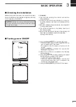
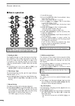
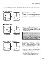
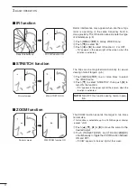
1
■
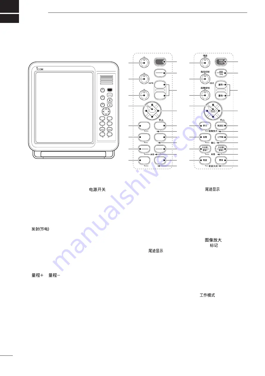
Front panel
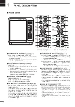
q
POWER SWITCH [POWER]/[
]
(p. 9)
Push to turn the radar power ON or OFF.
• The standby screen appears for 90 seconds while the
magnetron warms up.
• The initial screen appears and a beep sounds after the
power has been turned ON.
w
TRANSMIT/SAVE SWITCH [TX (SAVE)]/
[
]
➥
Push to toggle between the TX mode and the
standby mode. (p. 9)
➥
Hold down for 1 second to turn ON the power
save function. The radar for TX interval scan is
fixed at 10 revolutions. (p. 12)
• Select the save time in the INT. SETTING menu.
e
RANGE UP/ DOWN SWITCHES [+]/[–]/
[
]/[
]
(p. 9)
Push [
+
] to
increase the screen range.
Push [
–
] to decrease the screen range.
r
UP, DOWN, LEFT, RIGHT KEYS [
p
] [
q
] [
t
] [
u
]
Set the EBLs, VRMs, alarm area, ATA target, AIS
target and so on.
In the Menu screen, push [
p
] or [
q
] to select the
menu items, and then push [
t
] or [
u
] to select the
option or set the value.
In the normal operating mode, push a combination
of the [
p
]/[
t
] or [
p
]/[
u
], or [
q
]/[
t
] or [
q
]/[
u
] to
move the cross line cursor to the upper left or right,
or lower left or right.
t
TRAILS SWITCH [TRAILS]/[
]
(p. 12)
➥
Push to toggle the trail function ON or OFF. This
is useful for watching other ship’s tracks, and ap-
proximate relative speed.
• Trail Time can be set in the VIDEO menu.
➥
Hold down for 1 second to output the position
information where the cursor is placed, to the
NMEA output terminals.
• TLL output requires bearing data and position data.
y
ZOOM FUNCTION [ZOOM]/[
]
(p. 11)
Simultaneously push [TARGET]/[
] and [TRAILS]/
[
] to toggle the ZOOM function ON or OFF.
The ZOOM function enlarges the target to two times
normal size.
• Move the cursor to the target, then turn ON the function.
• The screen zooms the middle of the screen around your
own ship.
• This function is not usable in the
1
⁄
8
and the 32 NM or
higher ranges.
u
MODE SWITCH [MODE]/[
]
Push to select the Head-up (H UP), Course-up (C
UP), North-up (N UP) or True motion (TM) screens.
• The North-up and Course-up screens can be selected
only when a bearing data input is connected. (pp. 28,
43)
• The TM screen requires bearing data and LOG or posi
-
tion data. (pp. 28, 43)
• TheTM screen is not selectable in the 32 NM or higher
range.
TX
SAVE
TARGET
TRAILS
MODE
ALM
+
-
MOB
MENU
EBL2
VRM2
EBL1
VRM1
BRILL
ZOOM
OFF CENT
HL OFF
GAIN
SEA
RAIN
POWER
MOB
GAIN
SEA
RAIN
POWER
TX
SAVE
TARGET
TRAILS
ZOOM
ALM
MODE
OFF CENT
EBL1
VRM1
BRILL
MENU
HL OFF
EBL2
VRM2
AIS
TLL
AUTO
MARINE RADAR
MR-1200
e
r
q
w
t
u
o
!1
y
i
!2
!3
!4
!5
!6
!7
!8
!9
@0
e
r
q
w
t
u
o
!1
y
i
!2
!3
!4
!5
!6
!7
!8
!9
@0
!0
!0
Control panel (English)
Control panel (Chinese)

