3
8
BASIC OPERATION
■
Checking the installation
Before turning ON the power, be sure all the connec-
tions are complete. The checklist at right may be help-
ful for necessary confirmation.
CAUTION
:
Connect the scanner unit before turning ON
the power. Otherwise the magnetron inside the scanner
unit might be damaged.
D
Checklist
q
The four bolts securing the scanner unit must be
firmly tightened.
w
Cabling must be securely attached to a mast or
mounting material, and must not interfere with the
rigging.
e
Be sure waterproofing procedures are completed
on the system cable.
r
The power connections to the battery must be of
the correct polarity.
t
Be sure that the plugs at the rear of the display unit
have been connected correctly and securely.
(See page 28 for details.)
■
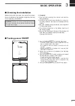
Turning power ON/OFF
1
(0.25)
T.VECT 6M
0.000NM
NM
CURS
SOG17.7KT
H UP
000.0˚T
HDG253.4˚T
E B L 1
E B L 2
MOB
V R M 1
V R M 2
CURS 3 4 ˚ 3 7 . 7 2 N 1 3 5 ˚ 3 4 .4 2 E
STBY
IR
COMPASS
GPS
1
(0.25)
T.VECT 6M
0.000NM
NM
CURS
SOG17.7KT
H UP
000.0˚T
HDG253.4˚T
E B L 1
E B L 2
MOB
V R M 1
V R M 2
CURS 3 4 ˚ 3 7 . 7 2 N 1 3 5 ˚ 3 4 .4 2 E
IR
COMPASS
GPS
0.45
R E V *.*
ROM OK
RAM OK
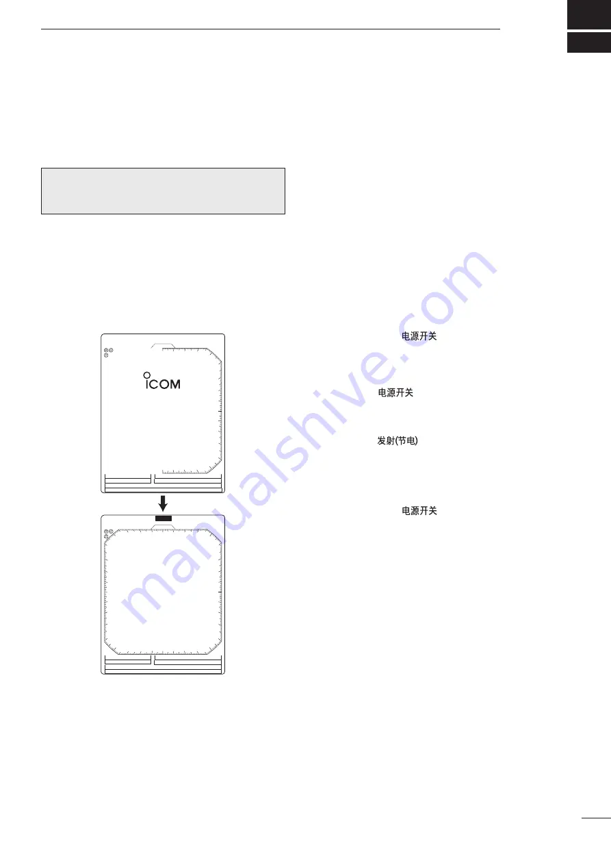
q
Push [POWER]/[
] to turn ON the power.
• The initial screen appears and the magnetron warm up
time is counted down on the screen.
•
The magnetron inside the scanner unit warms up for 90
seconds.
• [POWER]/
[
]
is disabled for 2 seconds after
the power is turned OFF.
w
When the countdown is completed, the Standby
screen appears.
e
Push [TX]/[
] to start scanning and select
the Plan Position Indicator (PPI) screen.
• Targets and heading markers appear.
• The screen appears approximately 2 seconds after
turning ON the power, when ‘AUTO’ is selected in the
“TUNE” item of the VIDEO menu.
r
Push [POWER]/[
] to turn OFF the power.

