7
-
2
PRELIMINARY CHECKS
7
-
2
-
1
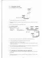
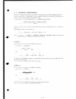
TRANSMITTE R OUTPUT CHE CKS
Power
Supply
8.4V or Battery ( IC-CM3)
1.
Connect a 50 ohms RF wattmeter to the ANT connector.
50S1
Power M.
2.
Setting the
I
C-H 12 to any programmed channel and key the transmitter. Observe the RF power
OUTPUT.
3. Power output should be 2.5 watts at rated input voltage.
7
-
2- 2 R E CEIVE R CHE CKS
Make all checks at 8.4V DC
1. Settings of controls and switches
Power switch
ON
Squelch Control
Minimum position
Frequency
Any programmed channel
Oscillo
scope
EXT.
SP.
Audio
V.M.
Power
Supply
EXT SP
JACK
8.4V
2.
Connect an AF voltmeter to the SP jack and set the SOL control fully counterclockwise.
3. Connect the RF output of a VHF signal generator to the ANT connector.
4. Adjust the VO L control and the AF voltmeter range.
S.G .
BNC
0
Adjust the VO L control for a full scale reading on the AF voltmeter. Don't change the VO L control
setting after this adjustment.
5. Set the signal generator to the receiving frequency and adjust the output level of the signal generator
until the AF voltmeter shows a 20dB decrease in reading.
6. The signal generator output voltage at this point is the 20dB quieting sensitivity.
7
-
3
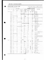
PREPARATION AND PROCEDURE BEFORE SERVICING
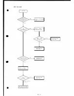
1.
Confirm defective operation and check to make sure setup or external sources are not the cause of
the problem.
2. Proper tools and measuring instruments are required for repair and adjustment. Don't try to repair
or modify without them.
7-2


