•
•
7
-
6
F REQUENCY PROG RAM M I NG
The
d
i
o
d
es
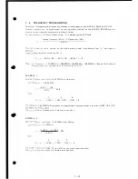
or programming frequency have been already placed on the MATRIX BOA R D of IC-H12 .
Desired
requency
can be
programmed by
cutting certain diode(s) on the MAT RIX BOA R D and the
or
l
a
or
e requency
programming
is shown below;
D
i i
d
e
d
numbers
in
the
Phase
Locked
Loop: "n" is determined by BC D code.
receive frequency (MHz) - LO frequency (MHz)
"n"
0 .015
a
1
x posi ion value
printed
on the
diode matrix board is subtracted from "n" until zero is
be s represent diode position: P
P
=
n
-
(
B
C
D x
100 ) - (BC D x
10)
-
(BC D x 1)
=
0
o e;
0
requenc
.
147 .995MHz ,
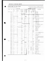
148. 000MHz, 148. 005MHz, 148.010MHz , (See on The Table of
F
r
eq
u
e
n
c
i
es
and' ' numbers to be utilized on the IC-H12.)
EXAMP L E
1.
es
·
e
c
eq
e
c
and ode:
154.570MHz, and Simplex.
0;
enc
=
148 .000MHz
154. 57 - 148
0 .015
4
------
438
3
8
--------
p
=
n -
400 )
(
N20, N10 )
-
(
N8 )
=
0
154. 570MHz Simplex can be programmed by placed diodes in positions N400 , N20, N10 ,
T
-
e Ex ra D
i
odes out for these matrix positions .
E
PL E
2.
en
c
and
Mode:
151. 025MHz, and Duplex.
.eo
e
c
= 147 .995MHz
51.025 - 147.995
0. 015
2
------
=
n
-
200 )
202
2
( N2 )
=
0
-�
es
·
-
200,
2, and
DUP. on the matrix board are used .
T-e-
:
�
e
E
ra
D
i
od
es out for
these matrix positions .
7 - 10


