•
•
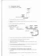
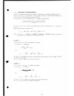
AF
Millivolt-
meter
3
.
od la ion check
AF
Oscillator
Power
Supply
(8.4V)
0
Dummy
Load
Directional
Coupler
Deviation
Meter
a
imum
de
i
at
i
on
.
:
With
1KHz 12 0mV shall be
4. SKHz
±10%.
odula ion
sensitivity:
Mic
input
voltage 12mV ± 3dB at 1 KHz. Deviation should be 3. 5KHz.
S
Ra io:
Connect he
output
of
the deviation
meter to a millivoltmeter. With no audio input to the mic
a
e he
oltmeter
reading . Now
apply 1 KHz 4 0mV audio into
the
mic connector. Take
e er reading. The ratio should be greater than 40dB.
C
.
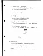
Sp ious Radiation
spectrum analyzer with appropriate attenuator. Confirm nearby random spurious signals
belo
·
undamental
signal less than
-60dB
.
. �eas
re
e
harmonic
wave
output, adjust RF-ATT until noise level just appears.
S
o
I
be less
than
-6 0dB below the fundamental signal.
7
·
5
·
3
R EC E I VE R
e c annel
select
switch at a programmed channel (center frequency of the operating fre
e
cy
ange
is
recommended).
Adjust L217 and L218 for maximum output on an RF voltmeter
ed o R257 .
•
re, se
-
e channel
select switch at
a high edge frequency channel and adjust
L217
and
L218
e procedure .
e procedures to obtain the same reading on the RF voltmeter on either channel.
pJ
ol age should be about 200mV.
3
=
1
-
E
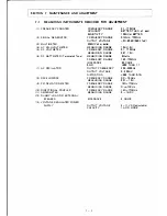
Coil
djustment.
connec ing
point
of measuring
instruments
and the setting of the knob.
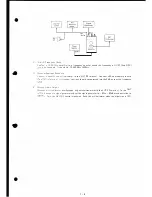
2
nel
se
l
ec s
i
ch
at a
programmed
channel.
•
""ec:
a
s
i
g
a
l
gene
a
or
o the
antenna
connector.
•
a, e ernal
speaker and
AF millivoltmeter to the
EXT SP
term inal.
inimum
range)
to Pin 16 on IC101
in
the IF , adjust L101 through L105
·
ile
set
ing
the
input
from the signal generator as low as possible. Then
vary
he
signal
generator ±1
OK Hz.
Check if rippling (change in output
er 3dB. readjust L 105.
or
outpu
to -80dBm
to -90dBm and deviation to 3. 5KHz.
Set signal
o speaker output maximum. After that, adjust L 1 07 for maximum output .
7-8


