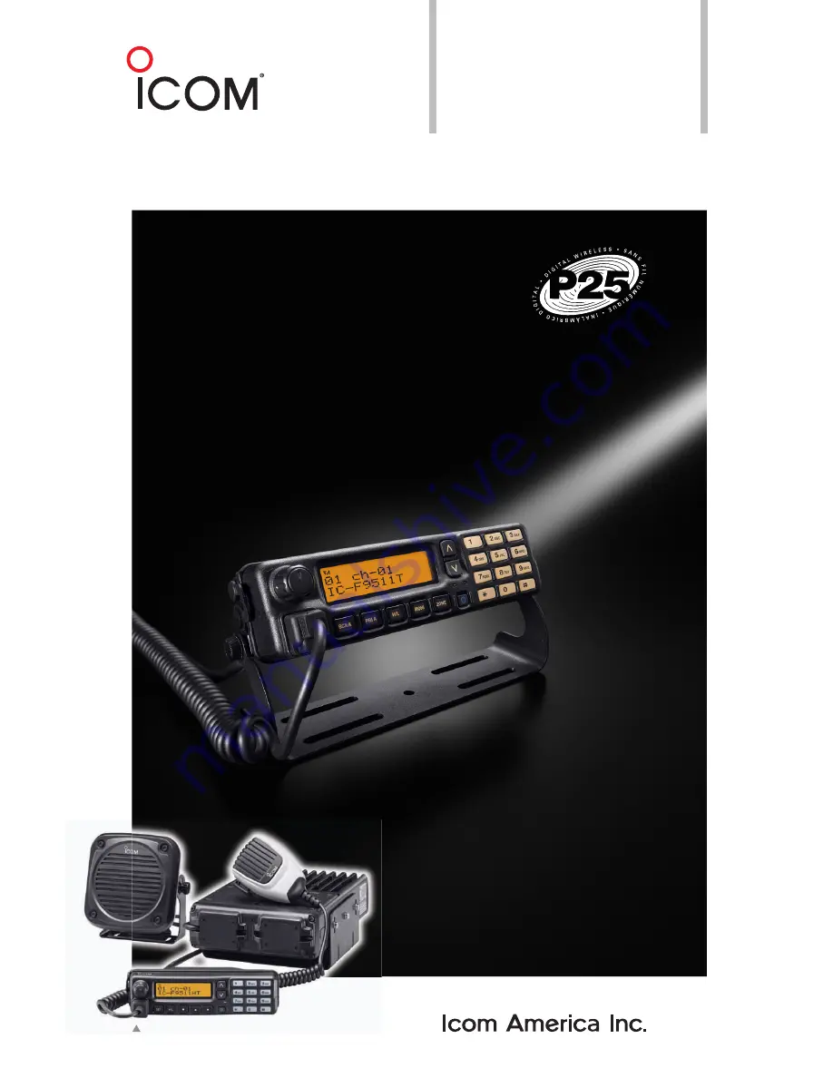
IC-F9511
RadioÊG uide
YourÊ Smart
P25Ê Choice
P25ÊT runking
P25ÊCon ventional
AnalogÊCon ventional
ALLÊINÊONE
NovemberÊ 2009
110WÊH ighÊPo weredÊF 9511HTÊV ersionÊSho wn
Page 1: ...IC F9511 Radio G uide Your Smart P25 Choice P25 T runking P25 Con ventional Analog Con ventional ALL IN ONE November 2009 110W H igh Po wered F 9511HT V ersion Sho wn...
Page 2: ...185 795 5 164 986 5 185 795 and 5 146 497 IPR means Intellectual Property Rights Document Copyrights No duplication or distribution of this document or any portion thereof shall take place without th...
Page 3: ...rammable Functions Keys IC F9511S IC F9511T 28 4 1 4 Operation and Function IC F9511HT 30 4 1 5 Function Display IC F9511HT 31 4 1 6 Programmable Functions Keys IC F9511HT 32 4 1 7 Preparation for Ope...
Page 4: ...at has not shifted production to lower cost countries but kept its production base 100 in Japan production to lower cost countries but kept its production base 100 in Japan The Wakayama Icom plant has...
Page 5: ...nsceivers USA Version USA Version EXP Version EXP Version IC F9511HT includes supplied Hand Microphone HM 148G and Optional External Speaker SP 30 Photo Double remote head option IC F9511S IC F9521S I...
Page 6: ...es conforms to the standard specifications for TIA 102 CAAB B Digital C4FM Transceiver Performance recommendations Digital Analog Mixed mode operation The IC F9510 series have the mixed mode operation...
Page 7: ...e RF unit dimensions are only 175 W 279 D 60 H mm so the IC F9511HT can be fit into the letter size console box The controller and speaker are separated from the main RF unit for to the radio you can...
Page 8: ...decoder 1 and MDC 1200 Meets MIL STANDARD The MIL STD 810 series of standards are issued by the United States Army s Developmental Test Command to specify various environmental tests compatible 1 Ava...
Page 9: ...body such as the back of a hand P t t d i t f i lid bj t IP Level Description of Protection Level 0 Not protected 1 Protected against vertically falling water drops Protected against vertically fallin...
Page 10: ...from the widest range of equipment and features Provide user friendly equipment so users can take full advantage of their radios p vocoder converts speech into a digital bit stream Test panels judged...
Page 11: ...174 400 470 450 520 400 470 450 520 Number of Channels 512 ch 128 zones Channel Spacing kHz 12 5 digital 15 30 analog 12 5 digital 12 5 25 analog PLL Channel Step kHz 2 5 3 125 Current Drain Tx High 2...
Page 12: ...0 450 520 Number of Channels 512 ch 128 zones Channel Spacing kHz 12 5 digital 12 5 25 analog PLL Channel Step kHz 2 5 3 125 Current Drain Tx High 11A Rx Stand by 350mA Max audio 1000mA Dimensions W H...
Page 13: ...connect the accessories Mounting screws M5x12 Mounting bracket Flat washers Spring washers Nuts Bracket bolts 1 10 key type only Mounting screws M5 x 12 Self tapping screws M5 x 16 to this instructio...
Page 14: ...key cap as below Hand Microphone When using with the self ground type microphone hanger 1 Attach the microphone hanger with screws 2 Put on on hook or take off off hook the i h microphone Mounting the...
Page 15: ...ls Nuts M5 Bracket bolts Mounting bracket for controller Flat washers M5 Spring washers M5 Nuts M5 Self tapping screws M5x16 Bracket screws Function name s tickers 2 Fuses 1 Separation cable Crimp ter...
Page 16: ...mounting styles are available one is When using with the self ground type microphone hanger 1 Attach the microphone hanger with screws 2 Put on on hook or take off off hook the microphone overhead mo...
Page 17: ...main unit Main unit 1Unscrew the 4 screws of the front plate either the left or right then remove the front plate from the Separation cable connection CAUTION To avoid damage to the transceiver disco...
Page 18: ...can obstruct the driver s view mounted to the vehicle and should be a sensible size If you choose a magnetic mount type be sure that it is rated for the antenna type CABLING Mobile transceivers gener...
Page 19: ...you can proceed to battery you need to be aware of some possible problems 1 Is the vehicle fitted with an alarm that may not operate after re connection 2 Is the vehicle fitted with any electronic cir...
Page 20: ...ng MIC Mute Input 13 H_OUT1 22W Hi Power AMP BTL Output 14 GND Ground 15 PIO2 Port setting 16 NC No connection 17 PI03 Port setting 18 PI04 Port setting p g 23 PIN07 Output Mic Mute 24 Input Dimmer 25...
Page 21: ...rio A Rewrite Prio B Prio B Rewrite MR CH 1 MR CH 2 MR CH 3 MR CH 4 IC F9511S Moni Public Address RX Speaker Light Lock Lone Worker High Low Talk around DTMF A t di l Front A Unit IC F9511T Front B Un...
Page 22: ...elf ground OPC 1532 Mobile to mobile zone copy OPC 1871 Mobile to handheld zone copy SP 22 Compact and easy to install Same as SP 10 Compact mobile speaker SP 30 External speaker for IC F9511HT OPC 15...
Page 23: ...pplied with the transceiver Connected Not Connected N A N A 2 Hot DTMF for HM 148T The DTMF code will be sent out when pressing a key without a PTT operation This function can be de activated too Hang...
Page 24: ...RYPTION UNIT INSTALLATION AES DES Encryption Unit DES Encryption Unit 3Attach the unit as illustrated below IC F9511S IC F9511T 1Unscrew 4 screws A then remove the bottom cover 2Unplug J1 B and J6 C F...
Page 25: ...ation 2Replace the clock backup battery located on the MAIN UNIT as below Make sure the battery Fuse rating 20 A USE a 20 A fuse only for IC F9511S IC F9511T MAIN UNIT as below Make sure the battery p...
Page 26: ...igned by your dealer 10 KEYPAD 10 key model only The keypad allows you to enter digits to S l t h l t h l d DTMF y p RMK 2 Connector cover Select memory channels tone channels and DTMF codes when in t...
Page 27: ...system operations Consult your Icom dealer or system operator for details concerning your Appears when the channel is in the audible unmute condition COMPANDER INDICATOR Appears when the compander fu...
Page 28: ...n list selection mode PRIO A B KEYS Push to select Priority A or Priority B channel ZONE UP AND DOWN KEY This function is for DIAL only Rotate to select the desired zone ZONE KEY Push this key then pu...
Page 29: ...is connected to the D Sub 25 pin This function is available when the external speaker is additionally connected This function is useful when you are out of the vehicle The audio output level is linked...
Page 30: ...nsceiver may be damaged MICROPHONE The supplied microphone has a PTT switch and a hanger hook Connector cover operation Depending on the pre set value BUSY INDICATOR Lights green while receiving a sig...
Page 31: ...erations Consult your Icom dealer or system operator for details concerning your Appears when the channel is in the audible unmute condition COMPANDER INDICATOR Appears when the compander function is...
Page 32: ...hile pushing this key intended use for grouping For example Staff A and Staff B are assigned into a Business zone and John and Cindy are assigned to a Private zone SCAN A START STOP KEY Push to start...
Page 33: ...all programmable keys except the following Moni Light Lock Emergency Single Emergency Repeat Surveillance and OPT 1 2 3 LIGHT KEY Push to turn the transceiver s backlight ON for about 5 h th b klight...
Page 34: ...o B Rewrite 9 9 MR CH 1 2 3 4 9 9 Moni 9 9 Public Address 9 9 RX Speaker 9 9 Light 9 9 Lock 9 9 Programmable key functions availability Following chart shows the availability of the programmable key f...
Page 35: ...p FOACSU function is turned ON on the Trunking mode push to ignore the receiving call SCRAMBLER ENCRYPTION KEY Common operation LONE WORKER KEY Push to turn the Lone Worker function ON or OFF If the L...
Page 36: ...UERY PHONE and ANNOUNCEMENT After making the digital call type selection push this key again to enter the ID selection mode If STATUS or SHORT MSG is selected the operation While in the Trunking mode...
Page 37: ...o normal operation REKEY OTAR mode only Push and hold for 1 sec to transmit a Key M M KMM H ll d Management Message KMM Hello command to a Key Management Facility KMF to request rekeying KEYSET OTAR m...
Page 38: ...he channel to become clear The channel is busy when BUSY indicator lights In this instruction manual these keys are from the left called P0 P1 P2 P3 P4 eWh th PASSWORD i di ti d t The channel is busy...
Page 39: ...d date are not correct reset them gPush Clock to set The next item blinks hRepeat steps e to g to set items Time and date indication cPush Clock to indicate the current time and date on the LCD When t...
Page 40: ...mode The user set mode is accessed with User Set Mode and allows you to set seldom changed settings In Simple model only Sleep function The sleep function allows the transceiver to be automatically tu...
Page 41: ...t LCD Contrast Beep Beep Level Ringer Level SQL Level AF Min Level Mic Gain Horn Battery Voltage Signal Moni Lone Worker 2 and System Information 1 Simple model only 2 For the IC F9511S T this functio...
Page 42: ...and the specified time period has passed with no operation is performed the transceiver enters the emergency mode and then the countdown starts Emergency transmission When Emergency is pushed for the...
Page 43: ...target station is displayed after receiving a call Trunking mode only IMPORTANT for Trunking mode operation The public Trunking transceiver should be registered and group affiliated with the control c...
Page 44: ...the operating channel or turn power OFF then ON again to retry hunting y Site Select To edit the RFSS and SITE IDs 1 Push Site Select to select SITE 1 2 Push Site Select again to display the site info...
Page 45: ...Air Call SetUp FOACSU function 10 key models only To edit the Individual ID using the 10 keypad Input the Individual ID directly with the 10 keypad Push to clear a code When the Full Off Air Call Set...
Page 46: ...Depending on the pre set value 4 Release PTT to receive The Talk group ID or name is displayed for 2 sec on the upper line of the LCD when PTT is pushed This function can be turned OFF by your dealer...
Page 47: ...t the pager signal to the target station The Transmit indicator lights red PLEASE WAIT is displayed 5R l PTT Trunking mode 1 Push Digital Button to enter the digital call type selection mode 2 Push CH...
Page 48: ...ppears When the ID name is not programmed the ID code is displayed 4Push CH Up or CH Down or rotate 2An acknowledgement is automatically transmitted The Busy Transmit indicator does not light because...
Page 49: ...n Busy indicator lights green NO ACKNOWLDG is displayed when an acknowledgement is not received and the transceiver returns to normal operation Receiving When a remote monitor signal is received the t...
Page 50: ...ent only to a dispatcher in the Trunking mode 1Push Digital Button to enter the digital call type selection mode CH Up Down to select the desired ID or name Push and hold Digital Button for 1 sec to c...
Page 51: ...et station and then the transceiver returns to normal operation g g y Short Message selection mode In this case skip steps 2 and 3 Go to step 4 2Push CH Up or CH Down or rotate CH Up Down to select SH...
Page 52: ...owledgement is not received and the transceiver returns to normal operation Receiving 1When a Short Message is received The Busy indicator lights green 3Push Digital Button again to enter the Individu...
Page 53: ...Button or Phone to return to normal operation 6Push and hold PTT and speak into the microphone 7Release PTT to receive 8After the conversation is finished push Digital Button or Phone to disconnect th...
Page 54: ...the specified time period 2 after the emergency alarm transmission 1 Depending on the emergency repeat cycle setting 2 Depending on the pre set value microphone 5Release PTT to stop transmitting Recei...
Page 55: ...set time the calling station ID or name is displayed instead of the channel display The Transmit indicator lights red 4To exit the emergency mode turn the power OFF 1 The emergency repeat cycle must b...
Page 56: ...ely by sending a Rekey request to perform the rekey operation Change Active Keyset Change Group RSI Radio Check The transceiver automatically responds to any command From transceiver to KMF Registrati...
Page 57: ...er OFF 2While pushing P1 and P3 push to turn power ON CLEAR is displayed Turn power OFF to cancel clearing Creating the tactical group in zone 128 Zone copy 1Push CH Up or CH Down or rotate CH Up Down...
Page 58: ...d when CLONE is displayed the regular cloning operation is performed all data including zone 128 of the master transceiver is written to the sub transceiver For actual appearance of the cables please...
Page 59: ...y Mode Dialing function from the radio terminal to the telephone network indicating adaptability to the dialing g p y g message of the trunking packet 9 Unit to PSTN Explicit Dialing Buffered Mode Sam...
Page 60: ...roup Affiliation CAI Dynamic group function 35 Group Affiliation Static Dynamic group function 36 Roaming Roaming the trunking sites 37 Roaming Restriction Restrict roaming 38 RFSS Site Lock Restrict...
Page 61: ...or LwIP implementation UDP IP adaptable 51 SLIP PPP support for OS i f or LwIP implementation SLIP IP adaptable 52 SNDCP Subnetwork Dependent Convergence Protocol adaptable 53 Dual Mode Scanning Scann...
Page 62: ...ver installation is necessary The driver is supplied with the OPC 1862 1122U The USB driver supplied with the OPC 1862 hThe Choose Destination Location will appear as below Then click Next to install...
Page 63: ...Help 2 VIEW MENU View Selects the displayed font size Turn the tool bar indication ON or OFF 3 COM PORT MENU COM Port Click to display the COM port 1 to 4 and More setting dialog box Set the transfer...
Page 64: ...desired cell in the contents list screen directory or right click the cell to display the edit menu Then click Edit Enter to select and change the setting depending on the item 2Click Help to display...
Page 65: ...series VHF P25 TRUNKING HANDHELD TRANSCEIVERS and the IC F9510 series VHF P25 TRUNKING MOBILE TRANSCEIVERS Launching the CS F9010 F9510 Cloning Software 1 B f l hi g th g k th 1 Before launching the...
Page 66: ...e Enter up to a 12 character message that will be displayed at transmission and reception of a short message Ten messages are available OTAR OTAR O er The Air Reke ing is the common name Page Page cal...
Page 67: ...the scan type primary CH secondary CH TX CH Talkback CH Cancel CH and Text Key Display Assign the desired functions to the programmable function keys And set the keypad operation beep audio frequency...
Page 68: ...l not be performed and channel selection will continue to the next channel RFSS ID Enter the RF Subsystem RFSS ID for the system When SITE or RFSS is selected for the Coverage System Registration Home...
Page 69: ...st from 1 to 4 When the radio is powered on changes trunking system or goes out of range the radio will find a control channel in a valid area with the hunt list List control channels in the Hunt List...
Page 70: ...he number of times for Hunt Delta within the user s permission to accept the call Select OFF not to emit a beep and accept the call without asking permission from the user NOTE You can set the audio f...
Page 71: ...ming List List Operation CH ID Only Set a downlink frequency of a control channel in RX CH ID and RX CH Number CH Freq Only Set a downlink frequency of a RX CH ID Enter a control channel ID from broad...
Page 72: ...ry WACN ID Enter the Wide Area Communications Network WACN ID component of the Subscriber Unit SU ID for the roaming area Tx Offset Sign Select the Tx Offset Sign from Minus and Plus sign Tx Offset MH...
Page 73: ...ect the packet frame type for Key Management Messages KMMs exchanged between the radio and a Key Management Facility KMF Packet Data The radio transmits KMMs Registration and Deregistration using pack...
Page 74: ...the system as defined by TIA 102 BAEB section 6 2 5 Valid values are 0 through 15 corresponding to 1 through 16 state slots respectively SNDCP Version Enter the IP address of the Key Management Facil...
Page 75: ...requests Delayed Acknowledgment When transmitting more than one Delayed When transmitting more than one Delayed Acknowledgments the radio transmits acknowledgment at these intervals Response Kind Time...
Page 76: ...etwork Access Code from 000 to FFF hexadecimal code to separate the transceiver from the same adjacent channel station according to the assigned code The transceiver selectively accesses one of severa...
Page 77: ...he scan selection mode When a signal is detected on a channel other than Primary CH scan pauses until the signal di d P i CH i ti l Scan Type Set the scanning type to each scan group from 0 Scan OFF 1...
Page 78: ...nsmission ON or OFF The function allows you to transmit a signal on the channel that the scan stopped last when the transmission is performed during the scan stop the talk back timer after the resume...
Page 79: ...ctor CH Number Scan is cancelled in the selected Text Select the text indication capability from Text or Start CH during scan While the scan is pausing on a channel by receiving transmitting a signal...
Page 80: ...rs or symbols can be edited created in this sheet for a variety of i f ti i di ti information indication 1 Right click to display the Edit menu 2 Left click Edit Enter then the Character Editor screen...
Page 81: ...ency UT 125 UT 128 AES DES DES E ti U it E ti U it Encryption Unit Encryption Unit The AES Advanced Encryption Standard is a block cipher adopted as an encryption standard by the Federal Information P...
Page 82: ...EY WAITING 3 Using the soft keys just below the display in the KVL select the following in sequence Target Load Key y New 2 Enter the new key CKR This will be 5 numbers 0 and any number between zero a...
Page 83: ...s of key changing over the air Many of the newer NSA National Security Agency cryptosystems that use the 128 bit electronic key Benefits from using OTAR Brisk and efficient these are the words to desc...
Page 84: ...nct advantages over traditional CELP based vocoders Operating at data rates from 2 0 to 9 6 kbps the new AMBE 2 algorithm has achieved higher Mean Opinion Scores MOS than any other The vocoder speed s...
Page 85: ...page Please browse http www icomamerica com en default aspx Icom Global Site Icom America Inc Home page 1 Basic information about P25 These materials are downloadable from this site Please click here...
Page 86: ...ion manual M bil R di The following Materials are available upon request through local Icom Distributors in your region Operating Guide IC F9010 series IC F9510 series Instruction manual IC F9511S T I...
Page 87: ...IC F9511 Radio G uide 2380 116th Avenue NE Bellevue WA 98004 phone 425 454 8155 fax 425 454 1509 www icomamerica com For P eople W ho Make Smart Choices...