background image

2001 NEW

52

6

CONNECTION AND INSTALLATION

6

 Antenna

Most stations operate with a whip or long wire (insu-
lated back stay) antenna. However, these antennas 
cannot be connected directly to the transceiver since 
their impedance may not match with the transceiver 
antenna connector.


R

DANGER HIGH VOLTAGE!


NEVER

 touch the antenna element/wire while tun-

ing or transmitting.

q

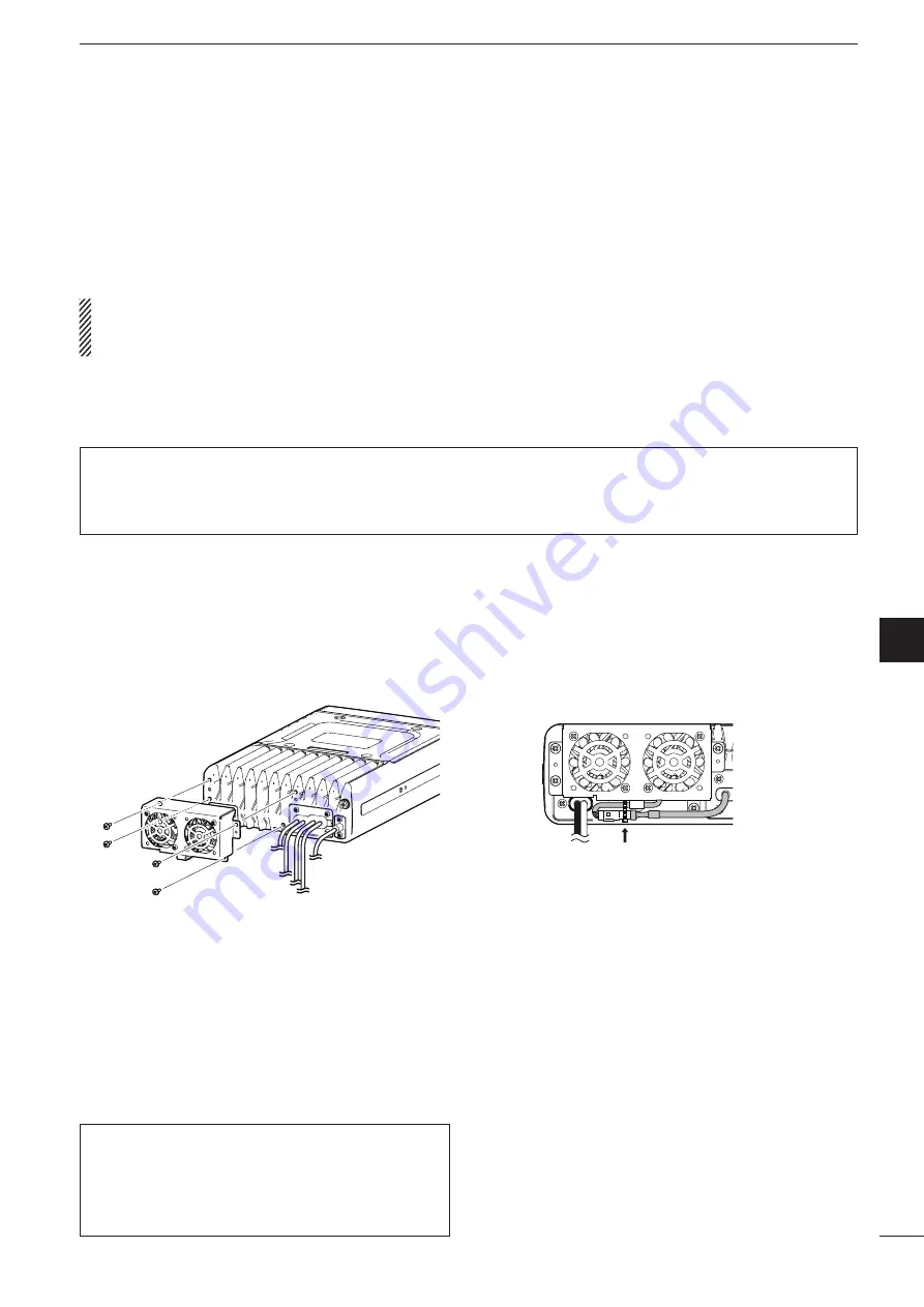
  Attach the Cooling fan to the transceiver’s heat-

sink, and tighten the 4 supplied M3 

×

 8 mm screws.

w

  Secure the connector and cables using the sup-

plied cable tie.

D

  AT-140


automatic


antenna


tuner

See page 50.

D

  Non-Icom tuner

Some  non-Icom  tuners  may  be  used  with  the  IC-
F8100. Please consult your dealer if you wish to use 
one. 

 CFU-F8100 (Optional Cooling Fan)

For Users in California (U.S.A.)

This  CR-1632  Lithium  Battery  contains  Perchlorate 
Material—special handling may apply.

See http://www.dtsc.ca.gov/hazardouswaste/perchlorate

Summary of Contents for IC-F8100

Page 1: ...HF TRANSCEIVER iF8100 INSTRUCTION MANUAL This device complies with Part 15 of the FCC Rules Operation is subject to the condition that this device does not cause harmful interference ...

Page 2: ... with Standard Australia Specification No AS NZS 4770 2000 FOREWORD i IMPORTANT i EXPLICIT DEFINITIONS i TABLE OF CONTENTS i PRECAUTIONS ii FCC INFORMATION iii SAFETY TRAINING INFORMATION iii INFORMATION EN MATIÈRE DE SÉCURITÉ iv 1 PANEL DESCRIPTION 1 7 Controller Front panel or HM 192 1 Rear panel 4 LCD screen 5 AD 119 Optional Junction Box 7 2 BASIC OPERATION 8 11 Power ON 8 Selecting display mo...

Page 3: ...aranteed within the specified operat ing temperature range However the LCD display may not be operate correctly or show an indication in the case of long hours of operation or after being placed in extremely cold areas DO NOT use harsh solvents such as benzine or alco hol when cleaning as they will damage the transceiver surfaces DO NOT push the PTT switch when you don t actually desire to transmi...

Page 4: ...ays adhere to the following guidelines DO NOT operate the radio without a proper antenna attached as this may damage the radio and may also cause you to exceed FCC RF exposure limits A proper antenna is the antenna supplied with this radio by the manufacturer or an antenna specifically autho rized by the manufacturer for use with this radio DO NOT transmit for more than 50 of total radio use time ...

Page 5: ...cées suffisamment loin d une antenne correcte ment fixée à l extérieur pour satisfaire aux exigen ces en matière d exposition aux RF en vertu des normes de conformité applicables MISE EN GARDE Afin de vous assurer que votre expo sition à une énergie électromagnéti que de RF se situe dans les limites permises par la FCC pour une utili sation grand public veuillez en tout temps respecter les directi...

Page 6: ...is ON Hold down for 2 seconds to turn OFF the power rCALL KEY Push to enter the Call menu Push again to go to the next screen in the Call menu tUP DOWN KEYS r s Selects the operating channel the items in the Menu mode and so on yENTER KEY 4 Push to enter or exit the selected Menu in the Menu screen uCLEAR KEY 8 Push to exit the Menu screen Push to return to the previous screen in the Call menu iHO...

Page 7: ...e input w MIC SW1 e AF r MIC SW2 t PTT y GND u GND microphone ground i 8 V DC output Max 10 mA 1LOCK KEY Hold down for 1 second to set the Key lock function to ALL NUMERIC KEY or OFF DKeypad Inputs numbers for the Clock Setting Inputs numbers characters or letters for the Sel call direct input 10 key Front panel HM 192 Selectable characters KEY INPUT INPUT KEY space Upper Lower case letters Number...

Page 8: ... the User Menu is set to OFF p 36 CLEAR TALK KEY C TALK Push to turn the Clear Talk function ON or OFF The C icon appears when the function is ON TUNER KEY TUNER Push to turn the Antenna tune mode to Auto Manual or OFF p 12 The Auto Tune or Manual Tune screen ap pears when the antenna tune mode is ON The SWR meter appears when the antenna tune mode is ON MUTE KEY MUTE Push to select the squelch ty...

Page 9: ...an external speaker such as the sup plied SP 25 r ACCESSORY CONNECTOR 10 PIN ACC1 t ACCESSORY CONNECTOR 12 PIN ACC2 Connects to the optional AD 119 junction box or OPC 2205 shielded control cable Both connectors must be connected to use the AD 119 or OPC 2205 NOTE Attach the connector caps when the op tional unit or cable is not used yANTENNA CONNECTOR Connects to a 50 Ω HF band antenna uGROUND TE...

Page 10: ...quelch is se lected V appears when the Voice squelch is selected yGPS ICON Appears when valid position data is received from a GPS receiver that is connected to the AD 119 or OPC 2205 uTIME DISPLAY Displays the time i FUNCTION DISPLAY Displays the function of the and func tion keys oSUB READOUTS Memory Channel display Shows the channel transmit and receive frequen cies The receive frequency is dis...

Page 11: ...ame is selected on the Selcall Address dis play The icon appears when a GPS Get Position call address name is selected on the Selcall Address dis play The icon appears when a Get Status call address name is selected on the Selcall Address display The icon appears when an RFDS Emergency call address name is selected on the Selcall Address dis play The icon appears when an Emergency call ad dress na...

Page 12: ...An tenna qUSB CONNECTOR USB Connects to a PC through an A B type USB cable w ACCESSORY CONNECTOR 2 12 PIN ACC2 e ACCESSORY CONNECTOR 1 10 PIN ACC1 Connects to the IC F8100 s Accessory connectors Both connectors must be connected to use this Junction Box rGROUND TERMINAL IMPORTANT Connects to a solid ground point tEXTERNAL MODEM CONNECTOR EXT MODEM Connects to an external unit such as an HF email m...

Page 13: ...OFF the power Power ON q Push one or more times to select the Memory Channel display The display sequentially selects Channel Selcall ALE Channel w Push r or s to select a desired memory chan nel Push one or more times to select a desired dis play mode The display sequentially selects Channel Selcall ALE Channel Memory channel display Selcall Address display ALE ID display Selecting a channel Sele...

Page 14: ... ON Push or to adjust the audio level If the squelch is closed push MUTE M one or more times to open the squelch The display shows the volume level while adjusting Minimum audio level Maximum audio level Squelch function Setting audio volume The scan function repeatedly scans programmed channels This function is convenient to wait for calls on multiple channels Stop q Push SCAN to start a scan Sca...

Page 15: ...nged it returns to the preprogrammed operating mode Depending on the transceiver version or prepro gramming some operating modes may not be selectable or usable except receive To prevent accidental channel changes or unneces sary function access use the Key Lock function The transceiver has two types of Key Lock functions Default q Hold down MENU HOME for 1 second to enter the Menu screen w Push r...

Page 16: ...ter the frequency setting mode e Push t or u to move the cursor to se lect the desired digit to change The cursor is displayed below the selected digit r Push r or s to change the frequency t Push 4 to exit the frequency setting mode Turning ON the split frequency function q Push A B to select VFO A or VFO B and separately set the receive and transmit frequen cies w Push Split to turn the split fr...

Page 17: ...er the an tenna tune mode The Auto Tune or Manual Tune screen sequentially appears When the transceiver is connected to an optional antenna tuner and Auto Tune screen is selected push 4 to start auto tuning The display shows the antenna SWR If the antenna cannot be tuned after 20 seconds the tuning circuit is automatically bypassed After tuning is finished the auto tune automatically stops transmi...

Page 18: ...r Hold down Default for 1 second to return to the default setting t Push MENU HOME twice to return to the nor mal operating screen ï Setting Microphone gain The microphone gain must be properly adjusted so that your signal is not distorted when transmitted Default q Hold down MENU HOME for 1 second to enter the Menu screen w Push r or s to select the User Menu and then push 4 e Push r or s to sele...

Page 19: ...eter reading ï Speech Processor The IC F8100 has a built in low distortion Speech Processor circuit This circuit increases your average talk power in the SSB mode and is especially useful when the receiving station is having difficulty hearing your audio Default q Hold down MENU HOME for 1 second to enter the Menu screen w Push r or s to select the User Menu and then push 4 e Push r or s to select...

Page 20: ...creen w Push r or s to select the User Menu and then push 4 e Push r or s to select Clarifier r Push u to turn ON the Clarifier function t Push MENU HOME twice to return to the nor mal operating screen Operation Upper shift Lower shift q Push CLAR 7 to turn ON the Clarifier function w Push or to tune the frequency shift The transmit frequency is not shifted Hold down Clear for 1 second to return t...

Page 21: ...e Preamp or Attenuator function t Push MENU HOME twice to return to the nor mal operating screen ï Noise Blanker The noise blanker reduces pulse type noise such as that generated by automobile ignition systems The noise blanker may distort reception of strong signals In such cases the noise blanker should be turned OFF q Hold down MENU HOME for 1 second to enter the Menu screen w Push r or s to se...

Page 22: ... AGC r Push t or u to select the desired AGC time constant FAST SLOW or AUTO When AUTO is selected the AGC time constant varies depending on the operating mode t Push MENU HOME twice to return to the nor mal operating screen D AGC OFF function When receiving weak signals with adjacent strong signals or noise the AGC function may reduce the sensitivity In this situation the AGC function should be t...

Page 23: ...ponents Push C TALK 8 to turn the Clear Talk function ON or OFF C appears when the Clear Talk function is ON Appears ï IF Filter selection The transceiver has three passband IF filter widths for each mode q Hold down MENU HOME for 1 second to enter the Menu screen w Push r or s to select the User Menu and then push 4 e Push r or s to select Bandwidth y Push t or u to select the IF filter width NAR...

Page 24: ...ded ID station to send its position information Get Status call Requests to send radio status information including power supply voltage signal strength output power VSWR and so on RFDS emergency call The RFDS Royal Flying Doctor Service emergency call uses a 2 Tone signal for an emergency call Emergency call Allows you to broadcast an emergency signal with own position information The Phone call ...

Page 25: ...Push HOME to return to the previous screen m Network selection Push t or u to select the Network y Push to go to the next screen Push HOME to return to the previous screen m Self ID selection Push t or u to select the Self ID m Self ID input Push Edit to enter the direct input mode Push the numeric keys to enter the Self ID Push 8 to delete the number This Self ID is overwritten or stored in the S...

Page 26: ... list m Phone address selection Push List to enter the list selection mode Push t or u to select the Phone address Push Edit to return to the direct input mode t Push to go to the next screen Push HOME to return to the previous screen m Phone Link selection Push t or u to select the Network m Phone Link input Push Edit to enter the direct input mode Push the numeric keys to enter the Phone Link Pu...

Page 27: ... can also transmit a Phone call when the Selcall Address is displayed In this case you can skip steps q to r above after selecting the Phone call address After a Phone call q When a Phone call is finished push to enter the Selcall menu TEL DISCONNECT appears If desired push HOME to return to the previous screen w Then push to transmit the disconnect call Until TEL DISCONNECT is transmitted the tel...

Page 28: ... HOME to return to the previous screen m Message selection Push t or u to select the Message m Message input Push Edit to enter the direct input mode Push the numeric keys to enter the Message Push A a to select the character group ABC Upper case letters abc lower case letters or 123 numbers Push 8 to delete the character This Message is overwritten or stored in the Mes sage list Push List to retu...

Page 29: ...l with your individual ID it automatically responds by trans mitting The received Message is stored in the Call In memory q After receiving a Message call and push any key to enter the Call In memory w Push More or Prev to select the informa tion e Push HOME to return to the normal operating screen ...

Page 30: ...revious screen m Network selection Push t or u to select the Network y Push to go to the next screen Push HOME to return to the previous screen m Self ID selection Push t or u to select the Self ID m Self ID input Push Edit to enter the direct input mode Push the numeric keys to enter the Self ID Push 8 to delete the number This Self ID is overwritten or stored in the Self ID list Push List to ret...

Page 31: ...on Push t or u to select the Network y Push to go to the next screen Push HOME to return to the previous screen m Self ID selection Push t or u to select the Self ID m Self ID input Push Edit to enter the direct input mode Push the numeric keys to enter the Self ID Push 8 to delete the number This Self ID is overwritten or stored in the Self ID list Push List to return to the list selection mode u...

Page 32: ...r u to select the Network y Push to go to the next screen Push HOME to return to the previous screen m Self ID selection Push t or u to select the Self ID m Self ID input Push Edit to enter the direct input mode Push the numeric keys to enter the Self ID Push 8 to delete the number This Self ID is overwritten or stored in the Self ID list Push List to return to the list selection mode u Push to en...

Page 33: ...AGE SEND PO SITION GET POSITION GET STATUS EMER GENCY CHANNEL TEST and RFDS EMERGENCY are selectable r Push to enter the Channel Menu and then push t or u to select the desired operat ing channel Push HOME to return to the Selcall menu t Push to transmit the RFDS emergency call The call is stored in the Call Out memory While calling push PTT to cancel the call You can also transmit an RFDS emergen...

Page 34: ...next screen Push HOME to return to the previous screen m Self ID selection Push t or u to select the Self ID m Self ID input Push Edit to enter the direct input mode Push the numeric keys to enter the Self ID Push 8 to delete the number This Self ID is overwritten or stored in the Self ID list Push List to return to the list selection mode u Push to enter the Channel Menu and then push t or u to s...

Page 35: ...ter the list selection mode Push t or u to select the Call ID Push Edit to return to the direct input mode t Push to go to the next screen Push HOME to return to the previous screen m Network selection Push t or u to select the Network y Push to go to the next screen Push HOME to return to the previous screen m Self ID selection Push t or u to select the Self ID m Self ID input Push Edit to enter ...

Page 36: ...stored in the Call Out memory While calling push PTT to cancel the call You can also transmit an Individual call when the ALE ID is displayed In this case you can skip the Call selection After an ALE call q After an ALE call is finished push any key to enter the ALE menu While linking the ALE call TERMINATION appears w Push to transmit a disconnect call Until TERMINATION is transmitted the channel...

Page 37: ...all to ALE then push to enter the ALE menu e Push t or u to set the ALE type to SOUNDING INDIVIDUAL NET SOUNDING and AMD are se lectable r Push to go to the next screen Push HOME to return to the previous screen m Self ID selection Push t or u to select Self ID t Push to enter the Channel Menu and then push t or u to select the desired operat ing channel Push HOME to return to the ALE Menu y Push ...

Page 38: ...next screen Push HOME to return to the previous screen m ALE Message selection Push t or u to select the ALE Mes sage u Push to enter the Channel Menu and then push t or u to select the desired operat ing channel Push HOME to return to the ALE Menu When Auto is selected the transceiver automatically selects the best quality channel in sequential order using the LQA table i Push to transmit an ALE ...

Page 39: ...e numeric keys 0 to 9 to edit the time Push t or u to move the cursor t Push 4 to save the time y Push MENU HOME twice to return to the normal operating screen q Hold down MENU HOME for 1 second to enter the Menu screen w Push r one or more times to select the Edit Menu and then push 4 e Push s once to select the UTC Offset Setting and then push 4 again r Push t or u to adjust the offset time Hold...

Page 40: ...ime period OFF Never lights BEEP Level Adjust the confirmation beep level to between 0 OFF and 50 Maximum in 1 digit steps Default 30 When the Advanced User Menu in the Admin Menu is set to OFF these items are not displayed In this case only the LCD Contrast LCD Dimmer Backlight BEEP Level Squelch Level Noise Blanker RF Power and Mic Gain values can be adjust ed or the settings selected User Menu ...

Page 41: ... Set the Automatic gain control settings to FAST SLOW or AUTO Default AUTO Bandwidth This item appears when the Advanced User Menu in the Admin Menu is set to ON Set the IF filter passband width to NARROW MID or WIDE Default WIDE Clarifier This item appears when the Advanced User Menu in the Admin Menu is set to ON Set the Clarifier function capability ON or OFF Default OFF When this setting is ON...

Page 42: ...crophone gain to between 0 Minimum and 10 Maximum in 1 digit steps Default 6 Key Lock This item appears when Advanced User Menu in the Admin Menu is set to ON Turn the Lock function ON or OFF You can select the two types of Lock functions ALL or NUMERIC KEY Default OFF Side Tone Level This item appears when Advanced User Menu in the Admin Menu is set to ON Adjust the CW side tone level from 0 OFF ...

Page 43: ...dministrator mode Repeatedly push A a to select the character group ABC upper case letters abc lower case letters or 123 numbers Push 8 to delete a character Push t or u to move the cursor Keypad D Return to the User mode q Turn OFF the transceiver power if the transceiver is powered ON w While holding down HOME push to turn ON the transceiver power to return to the User mode D Entering the Admin ...

Page 44: ...g This allows you to mute receiving the time delay ends after you stop keying Turn ON the CW Break In function and sets the delay to 0 5 1 2 or 3 seconds or OFF Default 2 0sec AGC Turn the Automatic gain control function ON or OFF Default ON Clear Talk Level The Clear Talk function adjusts signals in the pres ence of noise using the DSP circuit This item adjusts the Clear Talk Level from 1 Minimum...

Page 45: ...ode to INTERNAL EX TERNAL or OFF Default OFF Data Mode 1 Set Data Mode 1 to S4539 M188 110B S4285 S4529 S4415 M188 110A or FSK Default S4539 Data Mode 2 Set Data Mode 2 to S4539 M188 110B S4285 S4529 S4415 M188 110A or FSK Default M188 110B Data Mode 3 Set Data Mode 3 to S4539 M188 110B S4285 S4529 S4415 M188 110A or FSK Default FSK FSK Tone Several mark frequencies are used for FSK operation Set ...

Page 46: ...or OFF Default OFF When set to OFF the transceiver automatically an swers back if your station ID is called Selcall Time Out If you are calling a specific station but no answer is received then the transceiver cancels waiting for an answer back after this time period Set the waiting time for the Selcall answer back while calling Default 60 sec D Admin Menu items Continued Scan Auto Start Sets the ...

Page 47: ...smis sion only or disable Default RX TX Phone Mode Set the activation of Phone call to both reception and transmission reception only transmission only or dis able Default RX TX Channel Test Mode Set the activation of Channel Test call to both recep tion and transmission reception only transmission only or disable Default RX TX Send Position Mode Set the activation of Position transmitting call to...

Page 48: ...e ALE scanning group to between 1 and 100 Default 1 ALE Auto Sounding The Auto Sounding function allows users to deter mine the signal quality Set the Auto Sounding interval to 30 minutes 45 min utes 1 hour 2 hours 3 hours 4 hours 8 hours 16 hours or OFF Default OFF ALE Scan Speed Set the scan speed for the ALE and Call scans to HIGH MID or LOW Default HIGH ALE Auto Sounding Group Set the ALE Auto...

Page 49: ...iver automatically an swers back if your station ID is called When set to ON the transceiver ignores the call ALE Error Threshold Set the Error threshold level to between 0 and 4 for ALE communication quality Default 0 When errors detected by BER threshold or Golay threshold are over this setting communication is not possible ALE Call Retry Set the retry times to between 0 OFF and 99 when the call...

Page 50: ...steps or AUTO Default AUTO AUTO The same setting as your scan channels Emer Link Interval Set the interval time period of the Emergency Link function to between 10 and 300 seconds in 10 sec onds steps Default 120sec The transceiver will sequentially send a Selcall to the specified stations RFDS TX Time Set the time period of the RFDS call emission length to between 10 and 60 seconds in 1 second st...

Page 51: ...l modem BIT Display Set the activation of the Built in Test display to ON or OFF Default ON When set to ON the transceiver displays the device check screen after turning ON the power CI V Address To distinguish equipment each CI V transceiver has its own Icom standard address in hexadecimal code The IC F8100 s address is 82h Default 82h If you want to initialize the operating settings in the User ...

Page 52: ...es ATC 30 A 2 u Microphone hanger kit 1 set i Crimp terminals 2 D Separated Type The following accessories are supplied with IC F8100 Separated type q Microphone 1 w External speaker 1 e DC power cable 1 r Rubber feet 4 t Black and red cables with fuse holders 1 set y Spare fuses ATC 30 A 2 u Microphone hanger kit 1 set i Crimp terminals 2 o Remote controller with mounting bracket 1 0 Separation k...

Page 53: ... with IC F8100 Remote control microphone type q Remote control microphone 1 w External speaker 1 e DC power cable 1 r Rubber feet 4 t Black and red cables with fuse holders 1 set y Spare fuses ATC 30 A 2 u Microphone hanger kit 1 set i Crimp terminals 2 o Extension MIC connector 1 The separation cable is not supplied and must be pur chased separately according to the cable length ...

Page 54: ... this ferrite EMI filter Only for USA versions R WARNING NEVER connect to a 24 V battery This will damage the transceiver 1 8 9 15 to IC F8100 MIC connector pin 5 to IC F8100 SP connector AF input FSK terminal unit AF ground Tx Rx control To pin 14 To pin 12 FSK connection AD 119 FSK keying Ground 1 8 9 15 To pin 14 To pin 12 CW key connection AD 119 To use FSK mode the Modem item in Admin Menu is...

Page 55: ... to a 13 8 V DC power source to ACC2 to ACC1 AD 119 DO NOT stretch the Ground wire This may cause a ground wire disconnection and or damage DO NOT pull the antenna and control cable re ceptacles This may cause a cable disconnection in the tuner unit inside connector damage or a bad connection Wrap both the antenna and the control cable con nectors with rubber vulcanizing tape and then wrap electri...

Page 56: ... a metal hull Use Zinc anodes to protect the hull from electroly sis Ask your dealer technical installer or refer to a technical book and so on for RF grounding de tails Ground system example Best ground points External ground plate Copper screen Copper foil Unusable ground points These connections may cause an explosion or electrical shock Gas or electrical pipe Fuel tank or oil catch pan Copper ...

Page 57: ...or transmitting q Attach the Cooling fan to the transceiver s heat sink and tighten the 4 supplied M3 8 mm screws w Secure the connector and cables using the sup plied cable tie D AT 140 automatic antenna tuner See page 50 D Non Icom tuner Some non Icom tuners may be used with the IC F8100 Please consult your dealer if you wish to use one CFU F8100 Optional Cooling Fan For Users in California U S ...

Page 58: ...crews Nuts M5 D Separation The optional OPC 607 3 m 9 8 ft OPC 608 8 m 26 2 ft OPC 609 1 9 m 6 2 ft or OPC 726 5 m 16 4 ft separation cable is required for separately in stalling the transceiver front panel and Main unit q First make sure the transceiver s power is OFF then disconnect the DC power cable w Remove the knob bolts and mounting bracket from the RMK 6 e Unscrew the 4 hex socket screws u...

Page 59: ...to either the left or right grooves on the back of the attachment Use the supplied screw M3 8 mm Rear plate Main unit attachment Cable groove Separation cable u Connect the connection cable coming from the RMK 6 as shown below Then tighten the 4 hex socket screws i Connect the other end of the Separation cable to the front panel attachment as shown below After the cable connection replace the remo...

Page 60: ...her the OPC 607 OPC 608 OPC 609 or OPC 726 separation cable to the Main unit at tachment as shown below After the connecting the cable replace the rear plate and the 4 screws The separation cable can be inserted into either the left or right grooves on the back of the attachment Rear plate Main unit attachment Cable groove Separation cable Use the supplied M3 8 screw e Connect the other side of th...

Page 61: ...n dered or where it could cause bodily injury NEVER place the main unit or remote controller where air bag deployment may be obstructed DO NOT place the main unit or remote controller where hot or cold air blows directly onto it DO NOT place the main unit or remote controller in direct sunlight D Mounting the controller or speaker Check the installation angle the display may not be easy to read at...

Page 62: ...g bracket as shown below Not supplied by Icom r The completed mounting should look like this Mounting on the board RWARNING Mount the mounting bracket with 4 supplied screws to a surface that is more than 40 mm 1 6 inches thick and can support more than 10 kg The unit must be mounted on only a flat hard surface D Mounting the transceiver A supplied mounting bracket is used to mount the transceiver...

Page 63: ...nger of electric shock equipment dam age and or fire or injury The IC F8100 has two fuse types installed for trans ceiver protection DC power cable ATC 30 A Circuitry fuse ATC 5 A D Internal fuse replacement q Turn the transceiver upside down w Unscrew 4 screws from the bottom cover then lift up the cover e Replace the circuitry fuse as shown in the diagram below Use the supplied ATC 5 A fuse r Re...

Page 64: ... 5 to 0 8 V while tuning 4 RL1 Goes to ground when transmitting 5 TUM4 Stepping motor control signal output for AT230 6 TUM3 Stepping motor control signal output for AT230 7 TUM2 Stepping motor control signal output for AT230 8 TUM1 Stepping motor control signal output for AT230 9 NC No connection 10 NC No connection 11 START Start bypass signal output 12 CWKEY CW and FSK keying input Input level ...

Page 65: ...d data 8 RTS Output for request to send data 9 NC No connection EXT MODEM Pin Pin name Description Specification 1 8 1 TXD Output terminal for receive data RS 232C 2 RXD Input terminal for transmit data RS 232C 3 GND Connect to ground 4 PTT PTT input terminal When grounded transmits 0 V transmit 5 V receive 5 AF GND Ground line for the AF signal 6 AF OUT Output terminal for the AF signal Output im...

Page 66: ...power typical AUS versions J3E HIGH 100 W p p MID 50 W p p LOW 10 W p p Other versions J3E A1A HIGH 125 W p p MID 50 W p p LOW 10 W p p A3E HIGH 30 W Carrier MID 12 5 W Carrier LOW 3 W Carrier F1B J2B HIGH 75 W p p MID 50 W p p LOW 10 W p p Spurious emission USA versions 64 dB below peak output power Other versions 64 dB typical below peak output power Carrier suppression 50 dB below peak output p...

Page 67: ... with the IC F8100 Separated Type Allows you to install the transceiver front panel separate from the Main unit for op erating convenience The RMK 6 requires either the OPC 607 OPC 608 OPC 609 or OPC 726 separation cable OPC 607 OPC 608 OPC 609 OPC 726 separation cable OPC 607 3 m 9 8 ft OPC 608 8 m 26 2 ft OPC 609 1 9 m 6 2 ft OPC 726 5 m 16 4 ft Recommended Automatic tuning antenna AT230 from Mo...

Page 68: ...63 MEMO ...

Page 69: ...64 1 2 3 4 5 6 7 8 9 10 11 12 13 14 15 16 17 Quick Reference MEMO ...

Page 70: ...65 MEMO ...

Page 71: ...66 1 2 3 4 5 6 7 8 9 10 11 12 13 14 15 16 17 Quick Reference MEMO ...

Page 72: ...1 1 32 Kamiminami Hirano ku Osaka 547 0003 Japan A 6916H 1EX w Printed in Japan 2011 2012 Icom Inc Printed on recycled paper with soy ink ...

Reviews: