13.
Touch
the
static-protective
package
that
contains
the
drive
to
any
unpainted
metal
surface
on
the
server;
then,
remove
the
drive
from
the
package
and
place
it
on
a
static-protective
surface.
14.
Set
any
jumpers
or
switches
on
the
drive
according
to
the
documentation
that
comes
with
the
drive.
15.
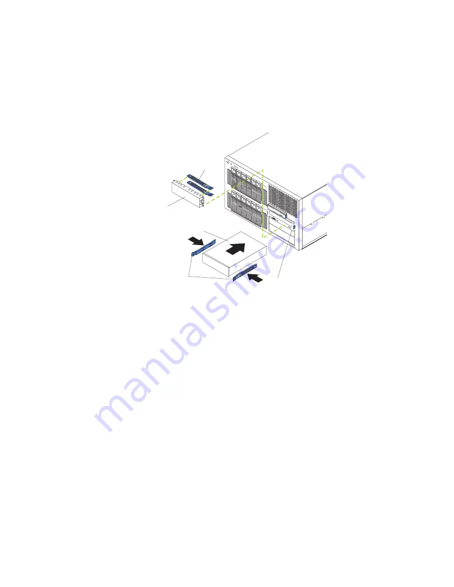
Install
the
drive:
See
the
following
illustration
when
installing
a
5.25-inch
removable-media
drive.
Blue slide rails
Slide rails
Filler panel
Non-hot-swap bay
Non-hot-swap
drive
v
Use
the
blue
plastic
slide
rails
that
come
with
the
server
as
described
in
this
step,
unless
the
drive
comes
with
custom
metal
slide
rails.
v
If
you
are
installing
an
SDLT
drive,
use
the
custom
metal
slide
rails
and
screws
that
come
with
the
option
package.
Follow
the
installation
instructions
that
come
with
the
option
package;
then,
continue
with
step
15c.
v
If
you
are
installing
a
full-high
DLT
drive,
use
the
custom
metal
slide
rails
and
screws
that
are
located
inside
the
server,
under
the
microprocessor
airflow
guide.
See
the
illustration
in
step
6
on
page
76
for
the
location
of
the
microprocessor
airflow
guide.
Follow
the
installation
instructions
that
come
with
the
option
package;
then,
continue
with
step
15c.
a.
Remove
the
blue
snap-on
slide
rails
from
inside
the
filler
panel.
b.
Clip
the
slide
rails
onto
the
sides
of
the
drive.
c.
Store
the
filler
panel
for
later
use.
d.
Align
the
slide
rails
on
the
drive
with
the
guide
rails
in
the
bay;
then,
slide
the
drive
into
the
bay
until
it
snaps
into
place.
16.
Connect
a
compatible
signal
cable
to
the
device
that
you
just
installed
(see
“System-board
internal
cable
connectors”
on
page
43
for
cable
locations):
v
If
you
installed
an
IDE
device,
connect
the
black
end
of
the
IDE
signal
cable
to
the
rear
of
the
IDE
device.
Make
sure
that
the
blue
end
of
the
IDE
signal
cable
is
still
connected
to
the
system
board.
v
If
you
installed
a
SCSI
device,
install
a
SCSI
signal
cable
by
attaching
one
end
of
the
cable
to
the
rear
of
the
SCSI
device
that
you
installed.
Attach
the
other
end
of
the
cable
to
the
internal
SCSI
connector
(J15)
on
the
system
board.
78
xSeries
255
Type
8685:
Hardware
Maintenance
Manual
and
Troubleshooting
Guide
Summary of Contents for XSERIES 255 TYPE 8685
Page 1: ...xSeries 255 Type 8685 Hardware Maintenance Manual and Troubleshooting Guide ERserver...
Page 2: ......
Page 3: ...xSeries 255 Type 8685 Hardware Maintenance Manual and Troubleshooting Guide ERserver...
Page 6: ...iv xSeries 255 Type 8685 Hardware Maintenance Manual and Troubleshooting Guide...
Page 20: ...10 xSeries 255 Type 8685 Hardware Maintenance Manual and Troubleshooting Guide...
Page 126: ...116 xSeries 255 Type 8685 Hardware Maintenance Manual and Troubleshooting Guide...
Page 189: ...Appendix B Related service information 179...
Page 190: ...180 xSeries 255 Type 8685 Hardware Maintenance Manual and Troubleshooting Guide...
Page 191: ...Appendix B Related service information 181...
Page 192: ...182 xSeries 255 Type 8685 Hardware Maintenance Manual and Troubleshooting Guide...
Page 193: ...Appendix B Related service information 183...
Page 194: ...184 xSeries 255 Type 8685 Hardware Maintenance Manual and Troubleshooting Guide...
Page 195: ...Appendix B Related service information 185...
Page 196: ...186 xSeries 255 Type 8685 Hardware Maintenance Manual and Troubleshooting Guide...
Page 209: ...Appendix B Related service information 199...
Page 210: ...200 xSeries 255 Type 8685 Hardware Maintenance Manual and Troubleshooting Guide...
Page 211: ...Appendix B Related service information 201...
Page 212: ...202 xSeries 255 Type 8685 Hardware Maintenance Manual and Troubleshooting Guide...
Page 213: ...Appendix B Related service information 203...
Page 214: ...204 xSeries 255 Type 8685 Hardware Maintenance Manual and Troubleshooting Guide...
Page 224: ...214 xSeries 255 Type 8685 Hardware Maintenance Manual and Troubleshooting Guide...
Page 225: ......
Page 226: ...Part Number 24P2936 1P P N 24P2936...


