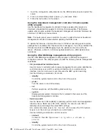
b.
Select
the
physical
drive
that
you
want
to
designate
as
the
hot-spare
drive,
and
click
the
icon
to
add
the
drive.
7.
Click
Next
.
The
“Configuration
summary”
window
opens.
8.
Review
the
information
in
the
“Configuration
summary”
window.
To
change
the
configuration,
click
Back
.
9.
Click
Apply
;
when
you
are
asked
whether
you
want
to
apply
the
new
configuration,
click
Yes
.
The
configuration
is
saved
in
the
controller
and
in
the
physical
drives.
10.
Exit
from
ServeRAID
Manager
and
remove
the
CD
from
the
CD-ROM
drive.
11.
Restart
the
server.
Viewing
the
configuration
You
can
use
ServeRAID
Manager
to
view
information
about
RAID
controllers
and
the
RAID
subsystem
(such
as
arrays,
logical
drives,
hot-spare
drives,
and
physical
drives).
When
you
click
an
object
in
the
ServeRAID
Manager
tree,
information
about
that
object
appears
in
the
right
pane.
To
display
a
list
of
available
actions
for
an
object,
click
the
object
and
click
Actions
.
Using
the
Scalable
Partition
Web
Interface
The
Scalable
Partition
Web
Interface
is
an
extension
of
the
Remote
Supervisor
Adapter
II
SlimLine
Web
Interface
and
is
used
to
create,
delete,
control,
and
view
scalable
partitions.
The
Scalable
Partition
Web
Interface
is
in
the
Remote
Supervisor
Adapter
II
SlimLine
integrated
service
processor.
The
scalable
partition
defines
a
multi-node
configuration,
which
interconnects
two,
four,
or
eight
servers.
The
multi-node
configuration
provides
the
function
to
individually
power-on
and
power-off
each
node.
The
multi-node
configuration
uses
a
single,
contiguous
memory
space
and
provides
access
to
all
associated
adapters.
Each
scalable
system
can
have
one
or
more
scalable
partitions.
Before
you
create
or
delete
scalable
partitions,
read
the
following
information:
v
A
Remote
Supervisor
Adapter
II
SlimLine
must
be
installed
in
all
nodes
that
are
to
become
part
of
a
scalable
partition.
v
All
of
the
service
processors
must
be
connected
to
an
Ethernet
network
through
the
SP
connector
on
the
rear
of
the
node.
This
connection
is
needed
so
that
the
service
processors
can
communicate
with
and
manage
scalable
partitions.
v
Make
sure
that
all
nodes
in
the
multi-node
configuration
have
the
current
level
of
BIOS
code,
SAS
BIOS
code,
service
processor
firmware,
BMC
firmware,
and
CPLD
firmware.
The
code
and
firmware
levels
must
be
the
same
for
all
nodes.
v
When
you
set
up
the
nodes
for
scalable
partitions
for
the
first
time,
you
must
first
log
on
and
configure
the
service
processor
in
each
node.
v
PCI
slot
numbering
starts
with
the
primary
node
and
continues
with
the
secondary
nodes,
in
numeric
order
of
the
logical
node
IDs.
Creating
a
scalable
partition
To
create
a
scalable
partition,
complete
the
following
steps:
1.
Make
sure
that
the
service
processor
on
each
node
is
configured
and
connected
to
the
network.
See
the
Remote
Supervisor
Adapter
II
SlimLine
and
Remote
Supervisor
Adapter
II
User’s
Guide
for
more
information.
Chapter
3.
Configuring
the
server
81
Summary of Contents for x3950 8872
Page 1: ...IBM System x3950 Type 8872 and System x3950 E Type 8874 User s Guide...
Page 2: ......
Page 3: ...IBM System x3950 Type 8872 and System x3950 E Type 8874 User s Guide...
Page 68: ...56 IBM System x3950 Type 8872 and System x3950 E Type 8874 User s Guide...
Page 98: ...86 IBM System x3950 Type 8872 and System x3950 E Type 8874 User s Guide...
Page 100: ...88 IBM System x3950 Type 8872 and System x3950 E Type 8874 User s Guide...
Page 109: ......
Page 110: ...Part Number 31R1856 Printed in USA 1P P N 31R1856...

