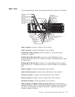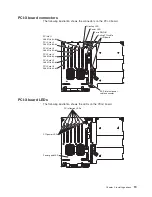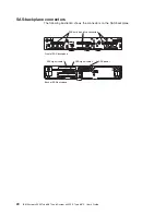
AC
DC
AC
DC
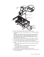
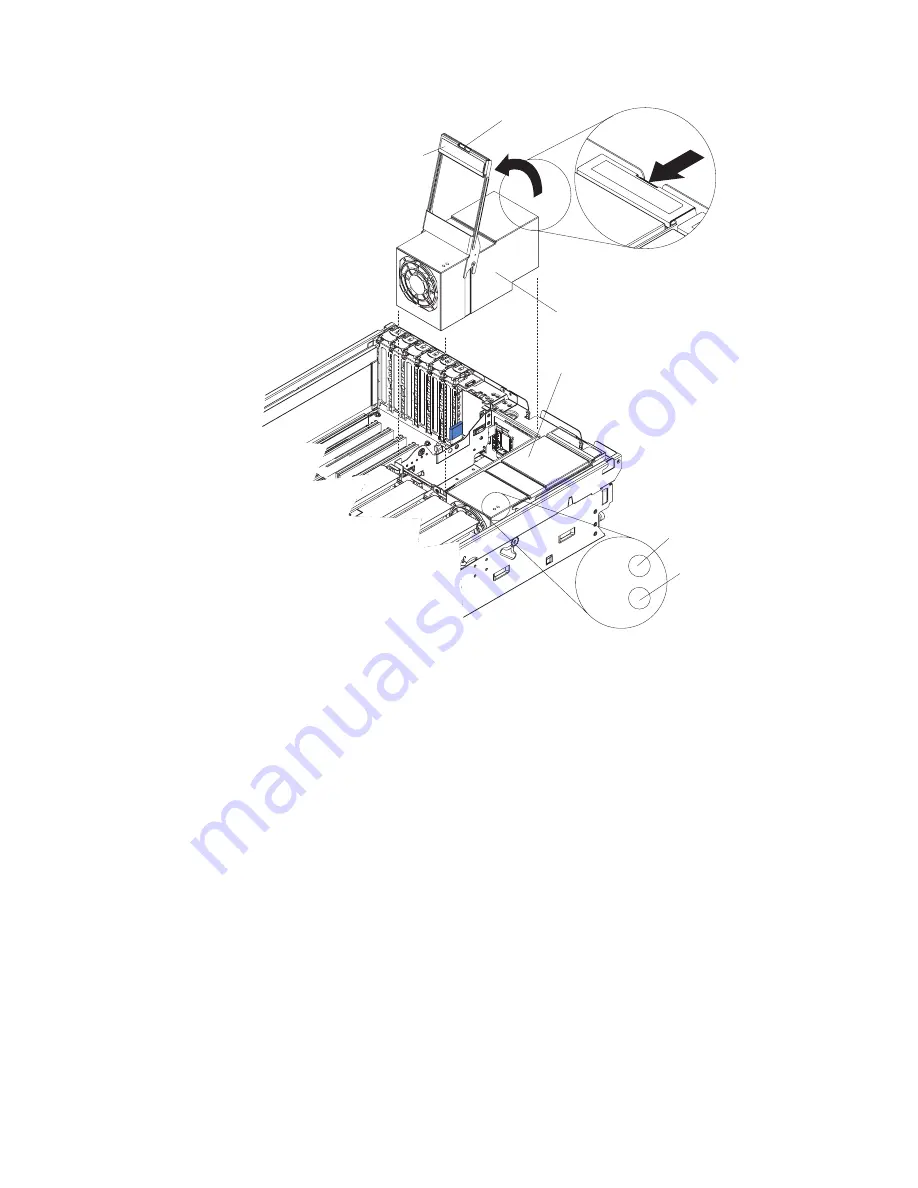
Locking handle
(open)
Locking latch
Power supply 2 (PS2)
Power supply 1 (PS1)
DC power
LED (green)
AC power
LED (green)
AC
DC
To
remove
a
hot-swap
power
supply,
complete
the
following
steps:
1.
Read
the
safety
information
that
begins
on
page
v
and
“Installation
guidelines”
on
page
21.
Attention:
Static
electricity
that
is
released
to
internal
server
components
when
the
server
is
powered-on
might
cause
the
server
to
halt,
which
could
result
in
the
loss
of
data.
To
avoid
this
potential
problem,
always
use
an
electrostatic-discharge
wrist
strap
or
other
grounding
system
when
working
inside
the
server
with
the
power
on.
2.
Remove
the
server
cover.
See
“Removing
the
cover
and
bezel”
on
page
23.
3.
If
you
are
adding
a
power
supply
to
an
empty
power-supply
bay,
remove
the
cover
from
the
ac
power
connector
opening
on
the
rear
of
the
server.
4.
If
you
are
replacing
a
failed
power
supply,
remove
the
failed
power
supply
from
the
bay:
a.
Disconnect
the
power
cord
from
the
connector
on
the
back
of
the
failed
power
supply.
b.
Press
the
locking
latch
on
the
power-supply
handle
and
raise
the
power-supply
handle
to
the
open
position.
c.
Lift
the
failed
power
supply
out
of
the
bay.
5.
Raise
the
handle
on
the
new
power
supply
to
the
open
position.
6.
Place
the
new
power
supply
into
the
power-supply
bay
in
the
chassis
and
fully
close
the
locking
handle.
Chapter
2.
Installing
options
25
Summary of Contents for x3950 8872
Page 1: ...IBM System x3950 Type 8872 and System x3950 E Type 8874 User s Guide...
Page 2: ......
Page 3: ...IBM System x3950 Type 8872 and System x3950 E Type 8874 User s Guide...
Page 68: ...56 IBM System x3950 Type 8872 and System x3950 E Type 8874 User s Guide...
Page 98: ...86 IBM System x3950 Type 8872 and System x3950 E Type 8874 User s Guide...
Page 100: ...88 IBM System x3950 Type 8872 and System x3950 E Type 8874 User s Guide...
Page 109: ......
Page 110: ...Part Number 31R1856 Printed in USA 1P P N 31R1856...

