background image

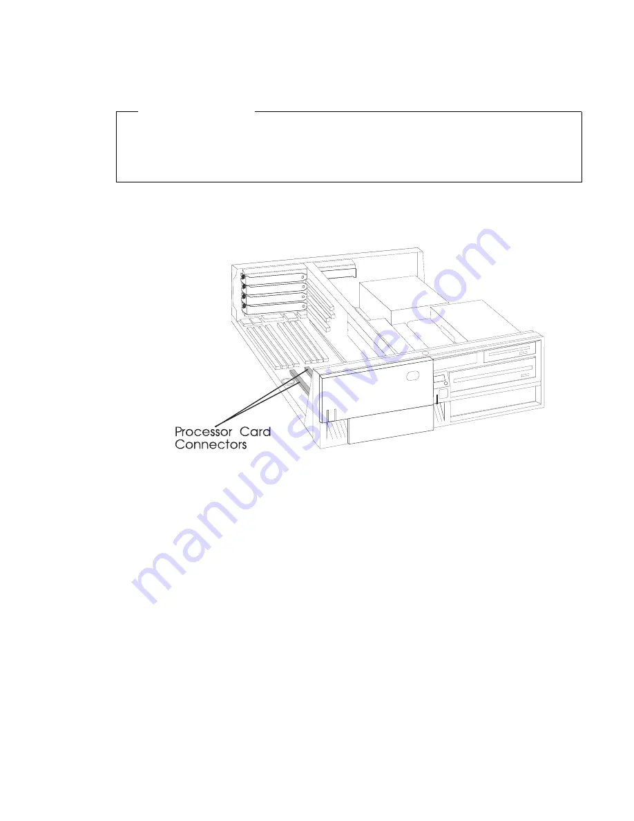
Removing a Processor Card (for the Model 240)

Before you begin:

Ÿ

Read “Safety Considerations” on page 4-2 and “Handling Static Sensitive
Devices” on page 4-3.

Ÿ

Remove the system unit cover (see “Removing the Cover” on page 4-4).

1. The processor cards are installed under the air duct near the front of the system

unit.

2. Remove any adapters that are blocking access to the air duct and the processor

card connectors (see “Removing Adapters” on page 4-80).

3. Remove the screw that holds the air duct to the system board.


Chapter 4. Installing and Removing Options

4-67

Summary of Contents for RS/6000 7043 43P Series

Page 1: ...RS 6000 7043 43P Series IBM User s Guide SA38 0511 03...

Page 2: ...publication at any time without notice It is possible that this publication may contain reference to or information about products machines and programs programming or services that are not announced...

Page 3: ...isions from packaging containers to subtle features of the architecture were based on these personal conversations and feedback sessions Our goal is to deliver high performance flexible solutions with...

Page 4: ...iv 7043 43P Series User s Guide...

Page 5: ...ycling and Disposal xix Battery Return Program xix Environmental Design xix About This Book xxi ISO 9000 xxi Related Publications xxi Chapter 1 System Startup 1 1 Before You Begin 1 2 Unpacking Your S...

Page 6: ...ot Menu Model 150 3 29 Utilities 3 33 Select Language 3 43 Open Firmware Command Line 3 43 Chapter 4 Installing and Removing Options 4 1 Available Options 4 1 Safety Considerations 4 2 Handling Static...

Page 7: ...e Diagnostics 7 2 Step 3 Running System Verification 7 3 Step 4 Additional System Verification 7 3 Step 5 Stopping the Diagnostics 7 4 Chapter 8 Hardware Problem Determination 8 1 Problem Determinatio...

Page 8: ...K NET FDDI Firmware 9 24 Format Media 9 25 Generic Microcode Download 9 28 Local Area Network Analyzer 9 28 Periodic Diagnostics 9 28 PCI RAID Physical Disk Identify 9 29 Process Supplemental Media 9...

Page 9: ...r Placement Notes B 1 Appendix C IRQ and DMA Channel Assignments C 1 IRQ Assignments C 1 DMA Channel Assignments C 2 ISA Adapter Configuration C 3 Index X 1 Reader s Comments We d Like to Hear From Yo...

Page 10: ...x 7043 43P Series User s Guide...

Page 11: ...rence by one or more of the following measures Reorient or relocate the receiving antenna Increase the separation between the equipment and receiver Connect the equipment into an outlet on a circuit d...

Page 12: ...echnical Commission IEC Statement This product has been designed and built to comply with IEC Standard 950 United Kingdom Telecommunications Safety Requirements This equipment is manufactured to the I...

Page 13: ...d of the Voluntary Control Council for Interference from Information Technology Equipment VCCI If this is used near a radio or television receiver in a domestic environment it may cause radio interfer...

Page 14: ...xiv 7043 43P Series User s Guide...

Page 15: ...eath or serious personal injury Danger notices appear on the following pages 4 2 A caution notice indicates the presence of a hazard that has the potential of causing moderate or minor personal injury...

Page 16: ...ents of the International Electrotechnical Commission IEC 825 1st edition 1984 and CENELEC EN 60 825 1991 for Class 1 laser products CAUTION A class 3 laser is contained in the device Do not attempt t...

Page 17: ...ru Philippines Puerto Rico Saudi Arabia Suriname Trinidad Taiwan U S A except Chicago Venezuela 2 62X0663 Chicago U S A Stackable 3 6952311 Argentina Australia New Zealand 4 13F9979 Abu Dhabi Austria...

Page 18: ...Index Part Number Country 8 14F0051 Liechtenstein Switzerland 9 14F0069 Chile Ethiopia Italy 10 14F0087 Israel 11 6952291 Paraguay Colombia Uruguay xviii 7043 43P Series User s Guide...

Page 19: ...ted States IBM has established a collection process for reuse recycling or proper disposal of used IBM batteries and battery packs For information on proper disposal of the batteries in this unit plea...

Page 20: ...xx 7043 43P Series User s Guide...

Page 21: ...lable The RS 6000 7043 43P Series Setup Instructions order number SA38 0510 is a pictorial guide designed to help you quickly set up your system unit if no internal modifications are needed The RS 600...

Page 22: ...xxii 7043 43P Series User s Guide...

Page 23: ...nect PCI bus which is faster than the industry standard architecture ISA bus The RS 6000 7043 43P Series Model 140 and Model 240 also offer an ISA bus to accommodate businesses that already have inves...

Page 24: ...keting representative Make sure you have an adequate number of properly grounded electrical outlets for your system unit display and any other options you intend to install Place your system unit in a...

Page 25: ...r ASCII terminal and optional devices make sure you have the following items System unit and power cord ASCII terminal mouse display and keyboard if ordered Your operating system and documentation Opt...

Page 26: ...32MB 64MB or 128MB dual inline memory modules with ECC EDO extended data out Diskette Drive Standard 3 5 inch 1 44MB Drives Hard Disk Drives 2 1GB fast wide SCSI 2 2 2GB 4 5GB 9 1GB high performance...

Page 27: ...board Optional 101 102 or 106 Enhanced Keyboard Standard 3 button mouse Front Panel Display 4 digit LED diagnostics display Input Output Ports 25 pin Parallel 9 pin Serial 2 8 pin Tablet Keyboard Mous...

Page 28: ...28MB or 256MB dual inline memory modules with ECC SDRAM EDO extended data out Diskette Drive Standard 3 5 inch 1 44MB Drives Hard Disk Drives 4 5GB and 9 1GB Ultra SCSI drives Maximum supported 3 inte...

Page 29: ...Front Panel Display 4 digit LED diagnostics display Input Output Ports 25 pin Parallel 9 pin Serial 2 8 pin Tablet Keyboard Mouse Ultra SCSI 16 bit 100 10 Base 5 Ethernet 100 10 Base T Ethernet Audio...

Page 30: ...owerPC 604 microprocessor is installed Memory 64MB 1024MB 8 memory module sockets for 16MB 32MB 64MB or 128MB dual inline memory modules Must be installed in matched pairs Diskette Drive Standard 3 5...

Page 31: ...101 102 or 106 Enhanced Keyboard Mouse 3 button Front Panel Display 4 digit LED diagnostics display Input Output Ports 25 pin Parallel 9 pin Serial 2 8 pin Tablet Keyboard Mouse SCSI 2 16 bit Fast Wid...

Page 32: ...kette and CD ROM drives when they are not in use 7 Cover Lock Security feature Prevents the cover from being removed and locks the media bay cover in the closed position 8 Diskette Drive status Light...

Page 33: ...V or 230 V setting available on specific systems Voltage selection is not needed on Model 150 as it uses an autoranging power supply 8 Security tether attachment Attachment point for a security tethe...

Page 34: ...y module kits to install go to Chapter 4 Installing and Removing Options on page 4 1 to install them After you complete option installation and have updated your configuration return to this chapter t...

Page 35: ...nnect that cable Connect the display power cord to the display If you are using an ASCII terminal Connect the ASCII terminal cable to the S1 port on the system unit Connect the ASCII terminal power co...

Page 36: ...r cord to the power connector on the system unit Secure the connection then plug the display power cord and the system unit power cord into properly grounded electrical outlets ATTENTION As soon as th...

Page 37: ...e rear of your system unit If the voltage range in your country is between 100 and 125 volts check to see that 115 is visible Use the 115 volt setting in the U S and Canada If the voltage range in you...

Page 38: ...p to you Use the following checklist as a guide Record your identification numbers Your system unit has important identification information that you might need if you have it serviced Appendix A Syst...

Page 39: ...unit is plugged into a grounded electrical wall outlet If this does not solve the problem go to Chapter 8 Hardware Problem Determination on page 8 1 When you turn on the system unit the Power LED come...

Page 40: ...wing illustration If the console selection screen appears each display and ASCII terminal attached to your system unit appears with a number To define a display or ASCII terminal as your system consol...

Page 41: ...lizes the keyboard and mouse When this icon appears you can choose one of several different startup options Pressing the F1 key activates the System Management Services Pressing the F5 or F6 key choos...

Page 42: ...turned off and turned on again to be reset If the power on password has been lost then the power on password jumper must be reset or disabled To reset the power on password remove the system unit pow...

Page 43: ...ist you in diagnosing system problems and observing system status When the system unit is turned on by pressing the power switch the power LED lights steadily The disk drive LED lights whenever the ha...

Page 44: ...fault boot list for a bootable image If a bootable image is found then the system unit loads and starts the operating system This is called a normal boot The system unit can also be booted from a cust...

Page 45: ...e is found in the custom boot list then the system restarts and attempts to boot again If the custom boot list is discovered to be corrupted the system rebuilds the custom boot list according to the d...

Page 46: ...agnostics loaded from CD ROM are called standalone diagnostics Since the default boot list checks the CD ROM drive before the disk drive this procedure is used to start standalone diagnostics 2 8 7043...

Page 47: ...he system console is a directly attached keyboard or the 6 key if the system console is an ASCII terminal 5 Enter any passwords Diagnostics loaded from a disk drive or network are called online diagno...

Page 48: ...unit starts online diagnostics Online diagnostics can only be used on system units installed with the AIX operating system Because the type of diagnostics started standalone or online depends on the s...

Page 49: ...de boot text based System Management Services starts F5 display keyboard Service mode boot default boot list 5 ASCII keyboard Service mode boot default boot list F6 display keyboard Service mode boot...

Page 50: ...the operating system Typewriter keys are similar to a standard typewriter Their function is controlled by the software Control keys move the cursor on the screen and do programmed control functions Th...

Page 51: ...s you move the mouse on a flat surface such as a desktop When you move the mouse around on a flat surface as shown in the following illustration the cursor moves on the display screen the movement cha...

Page 52: ...the mouse on the following surfaces Finished wood Glass Enamel Plastic Paper except newspaper Metal Rough surfaces collect contaminants that can be transferred to the interior of the mouse by the ball...

Page 53: ...ty wash it in warm soapy water Rinse and wipe the ball with a lint free cloth until dry 5 Inspect the ball cavity in the mouse for foreign materials If there are any foreign materials remove them 6 Re...

Page 54: ...tecting 3 5 Inch Diskettes Write protecting diskettes is necessary so that important information is not accidentally lost When diskettes are write protected you can read information from the diskettes...

Page 55: ...the labeled metal shutter first Push the diskette into the drive until you hear a click The click indicates that the diskette is securely in position in the drive To unload the diskette push the disk...

Page 56: ...Emergency Eject Access Load Unload Button Status Light Volume Control Head Phone Jack When the CD ROM is set to On the status light indicates one of several conditions The following are status light...

Page 57: ...on until the drawer comes out and then remove the disc Cleaning the CD ROM Drive This CD ROM drive has an internal head cleaning mechanism and therefore does not require an external cleaning device Th...

Page 58: ...ration below for the location of the emergency eject access 2 Push the tool in until some resistance is felt 3 Maintain a small amount of pressure on the rod while pulling on the tray with your finger...

Page 59: ...system unit is displayed at the bottom right hand corner of the initial logo screen Please note the version number processor upgrades may require a specified version of firmware to be installed in yo...

Page 60: ...After the System Management Services starts the following screen appears 3 2 7043 43P Series User s Guide...

Page 61: ...words control the playing of system tones enable the unattended start mode set and view the addresses of your system s SCSI controllers select the active console view or clear the firmware error log a...

Page 62: ...Selecting this icon makes it possible for you to view information about the setup of your system unit A list similar to the following appears when you select the Config icon 3 4 7043 43P Series User s...

Page 63: ...than one screen of information is available a blue arrow in the top right corner of the screen appears Use the Page Up and Page Down keys to scroll through the pages Chapter 3 System Management Servi...

Page 64: ...arious options regarding the operating system and boot sequence Note The SMS software on the Model 140 and Model 240 do not have this menu option On these systems this menu is replaced by the Boot men...

Page 65: ...system is installed then the system information in non volatile storage may have been lost This can happen if the battery has been removed To correct this situation refer to the bootlist reference in...

Page 66: ...change the custom boot list back to the default values click on Default If you change your startup sequence you must be extremely careful when performing write operations for example copying saving or...

Page 67: ...del 140 and Model 240 This selection enables you to view and change the custom boot list the sequence in which devices are searched for operating system startup code Chapter 3 System Management Servic...

Page 68: ...new order in the New column then select Save The List of Boot Devices is updated to reflect the order you have chosen You can choose 1 to 4 devices for the custom boot list To change the boot sequenc...

Page 69: ...les you to set password protection for turning on the system unit and for using system administration tools Audio Model 140 and Model 240 only Enables you to turn on or off the system tones heard when...

Page 70: ...to configure network adapters which require setup SCSI ID Allows you to view and change the addresses IDs of the SCSI controllers attached to your system unit Update Allows you to update the system f...

Page 71: ...icon is shown in the locked position if a power on password is not set then the Power On status icon is shown in the unlocked position as in the screen above When you select the Entry icon a screen w...

Page 72: ...d but not erase it move the power on password jumper as described in the section beginning on 4 9 Moving the jumper back to the default position re enables the power on password unless it has been rem...

Page 73: ...rn on whenever AC power is applied to the system instead of having the system unit wait for the power button to be pushed Privileged Access Password The privileged access password protects against the...

Page 74: ...ed and the privileged access password has been set great care must be taken to preserve the privileged access password If you set the privileged access password and later misplace it your system must...

Page 75: ...ly This icon enables you to turn on or off the system tones heard at power on time To change the audio status use the arrow keys or mouse to highlight the audio icon then press the Enter key Chapter 3...

Page 76: ...attached to your system Spin up delay values can be entered manually or a default setting can be used All values are measured in seconds The default is two seconds After you have entered the new Spin...

Page 77: ...or Log Selecting this icon displays the log of errors your system unit has encountered during operations Selecting the Clear icon erases the entries in this log Chapter 3 System Management Services 3...

Page 78: ...ote Initial Program Load RIPL icon above gives you access to the following selections The Set Address icon allows you to define addresses from which your system unit can receive RIPL code 3 20 7043 43...

Page 79: ...ange the improper address and select Save again The Ping icon allows you to confirm that a specified address is valid by sending a test transmission to that address After choosing the Ping option you...

Page 80: ...ystem to select the type automatically Use the arrow keys or mouse to highlight a selection To choose the highlighted selection press the spacebar then highlight the OK icon and press the Enter key Af...

Page 81: ...D highlight the entry by moving the arrow keys then enter another number After you have entered the new address use the arrow keys or mouse to highlight the Save icon and press the Enter key At any ti...

Page 82: ...w firmware image ATTENTION While the new firmware image is being copied into your system unit you must not turn off the system unit Turning off the system unit during the update process may render you...

Page 83: ...file on the firmware update diskette to precover img 3 Make sure your system unit is turned off 4 Insert the firmware recovery diskette into your system unit 5 Turn on your system unit 6 When the keyb...

Page 84: ...s starts the following screen appears Note The version of firmware currently installed in your system unit is displayed at the top of each screen in the text based System Management Services Please no...

Page 85: ...e 3 2 Text based System Management Services Main Menu Model 150 Selecting the numbered options provide capabilities described on the following pages After you have finished using the text based System...

Page 86: ...y slotA 8MB slotB 8MB LPT addr 3BC COM addr 3F8 COM addr 2F8 Audio Keyboard Mouse Diskette addr 3F Integrated Ethernet addr 8 5AF67BD SCSI cntlr id 7 P prev page N next page x Exit Figure 3 3 Text bas...

Page 87: ...ows the names of the operating system installed This option may not be supported by all operating systems In the case of AIX this is a supported option if you receive a message saying that No Operatin...

Page 88: ...Start Option Toggles between OFF and ON and selects if the Multiboot menu invokes automatically on startup or not Select Boot Devices This selection enables you to view and change the custom boot list...

Page 89: ...t Figure 3 6 Text based System Management Services Boot Sequence Screen Restore Default Settings Restores the boot list to the default sequence of The primary diskette drive CD ROM drive Tape id 5 Har...

Page 90: ...ed System Management Services Configure Boot Device Screen Attention If no user defined boot list exists and the privileged access password has been enabled you are asked for the privileged access pas...

Page 91: ...re 7 Select Console X Exit Figure 3 8 Text based System Management Services Utilities Menu Model 140 Model 240 Utilities 1 Set Passwords and Unattended Start Mode 2 Spin Up Delay 3 Display Error Log 4...

Page 92: ...rd again for verification If you previously had set a power on password and wanted to remove it select Remove Power On Password Notes 1 If you want to disable an installed power on password but not er...

Page 93: ...d access password immediately whenever it is changed Attention If no user defined boot list exists and the privileged access password has been enabled you will be asked for the privileged access passw...

Page 94: ...this option Here you can view or clear your computer s error log Error Log Date Time ErrorCode Location Entry 1 1 4 96 12 13 22 25A8 11 Entry 2 no error logged C Clear Error Log X Exit Figure 3 11 Te...

Page 95: ...ters 1 IP Parameters 2 Adapter Parameters 3 Ping X Exit Figure 3 12 Text based System Management Services RIPL Setup Menu Selecting the IP Parameters option displays the following screen IP Parameters...

Page 96: ...ardware address as well as configure network adapters that require setup Adapter Parameters Device HW Address 1 3Com 3C9 5 8 5AFC67BD 2 token ring 8 32E54A12 X Exit Figure 3 14 Text based System Manag...

Page 97: ...configuration menus 3Com Etherlink Fast XL 1 Media Type Auto 2 Full Duplex Auto X Exit Selecting the Media Type option allows you the change the media employed by the Ethernet adapter MEDIA TYPE 1 1...

Page 98: ...l Duplex 1 Yes 2 No 3 Auto Ping the last option available from the Network Parameters menu allows you to test a connection to a remote system unit After selecting the Ping option you must choose which...

Page 99: ...iew and change the addresses of the SCSI controllers attached to you computer Update System Firmware This option allows you to update your system firmware Note that you must insert a diskette containi...

Page 100: ...1 Locate your firmware update diskette 2 Using another system unit rename the img file on the firmware update diskette to precover img 3 Make sure your system unit is turned off 4 Insert the firmware...

Page 101: ...onfigure some adapters and the System Management Services makes it possible for you to view information about your system unit and to perform such tasks as setting passwords and changing device config...

Page 102: ...3 44 7043 43P Series User s Guide...

Page 103: ...procedures and component handling guidelines described in Safety Considerations on page 4 2 These precautions and guidelines help you work safely with your system unit or options Available Options Fo...

Page 104: ...wer cables for those devices are unplugged before the signal cables are connected If possible disconnect all power cables from the existing system before you add a device Use one hand when possible to...

Page 105: ...anti static package touch it to an unpainted metal part of the system unit for at least two seconds This drains static electricity from the package and from your body Remove the device from its packa...

Page 106: ...the floor stand when you remove the system unit cover 1 Unlock the cover lock and slide the drive bay cover all the way to the left 2 Remove any media diskette or CD from the drives 3 Shut down progra...

Page 107: ...all power cords cables from electrical outlets ATTENTION As soon as the system unit power cord is plugged in to the system unit and power outlet the power is on within the system unit whether or not...

Page 108: ...p of the system unit 9 While holding down the cover latch at the rear of the system unit slide the cover to the rear approximately 1 inch Grasp the cover on both sides and lift it away from the system...

Page 109: ...or Model 150 system unit use the following figure Note There are 6 memory DIMM slots on the Model 140 and 4 memory DIMM slots on the Model 150 To locate options in the Model 240 system unit use the fo...

Page 110: ...he Model 140 go to page 4 38 A 332 MHz processor upgrade for the Model 140 go to page 4 50 A processor card for the Model 240 go to page 4 63 An adapter go to page 4 70 Cabling for an Ultra SCSI adapt...

Page 111: ...ies or by removing the battery 2 If you forget the power on password you can erase the password by shutting down the system unit and removing the battery for at least 30 seconds See Changing the Batte...

Page 112: ...2 If you have a Model 140 locate jumper J90 using the following illustration 3 To disable the power on password move the jumper on J90 to the two rightmost pins 4 10 7043 43P Series User s Guide...

Page 113: ...If you have a Model 150 locate jumper J20 using the following illustration J20 5 To disable the power on password move the jumper to the two rightmost pins Chapter 4 Installing and Removing Options 4...

Page 114: ...the default position on the two leftmost pins You must also install all other options such as internal drives memory adapters if you are planning to install them now After you have installed these op...

Page 115: ...l 140 go to page 4 38 A 332 MHz processor upgrade for the Model 140 go to page 4 50 A processor card for the Model 240 go to page 4 63 An adapter go to page 4 70 Cabling for an Ultra SCSI adapter go t...

Page 116: ...e the jumper on the system board which blocks the use of the privileged access password This procedure should only be performed one time 1 Remove the disk drive bracket assembly from the system unit a...

Page 117: ...able or change the privileged access password first touch the metal frame of the system unit then gently pull upward on the small box jumper covering the pins Replace the jumper so that it covers the...

Page 118: ...2 b To enable or change the privileged access password first touch the metal frame of the system unit then gently pull upward on the small box jumper covering the pins Replace the jumper so that it co...

Page 119: ...two 5 Reinstall any adapters you have removed 6 To set the privileged access password you must first install all other options such as internal drives memory adapters if you are planning to install t...

Page 120: ...e Model 140 go to page 4 38 A 332 MHz processor upgrade for the Model 140 go to page 4 50 A processor card for the Model 240 go to page 4 63 An adapter go to page 4 70 Cabling for an Ultra SCSI adapte...

Page 121: ...before the interruption The factory setting for this capability is automatic power up disabled Note If the power on password is set then the system unit still turns on but does not boot unless the Rem...

Page 122: ...rame of the system unit then gently pull upward on the small box jumper covering the pins To enable the automatic power up feature place the jumper over the left two pins To disable the automatic powe...

Page 123: ...of the system unit then gently pull upward on the small box jumper covering the pins To enable the automatic power up feature place the jumper over the rear two pins To disable the automatic power up...

Page 124: ...l frame of the system unit then gently pull upward on the small box jumper covering the pins To enable the automatic power up feature place the jumper over the left two pins To disable the automatic p...

Page 125: ...MHz or 233 MHz processor upgrade for the Model 140 go to page 4 38 A 332 MHz processor upgrade for the Model 140 go to page 4 50 A processor card for the Model 240 go to page 4 63 An adapter go to pag...

Page 126: ...ory in the Model 140 1MB equals approximately 1000 000 bytes The memory module sizes for your system include 256MB 128MB 64MB 32MB and 16MB The available speed for these memory modules is 60 ns ATTENT...

Page 127: ...tall the new modules into the first available connector starting at slot A 1 Locate the memory module connectors To locate the six memory module slots in the Model 140 use the following figure Chapter...

Page 128: ...4 the second in slot 3 etc To locate the eight memory module slots in the Model 240 use the following figure 2 Remove any adapters that are blocking the memory module connectors see Removing Adapters...

Page 129: ...speed See the figure above 6 The memory modules are keyed so that they can only be inserted one way Align the memory module notches with the keys in the memory connector 7 Insert the memory module in...

Page 130: ...ly inserted into the socket 9 Reinstall any adapters you removed into their original connectors If you need further information for installing adapters see Installing Adapters on page 4 70 10 Go to De...

Page 131: ...l 140 go to page 4 38 A 332 MHz processor upgrade for the Model 140 go to page 4 50 A processor card for the Model 240 go to page 4 63 An adapter go to page 4 70 Cabling for an Ultra SCSI adapter go t...

Page 132: ...Handling Static Sensitive Devices on page 4 3 Remove the system unit cover see Removing the Cover on page 4 4 1 Locate the memory module connectors on the system board The memory module connectors fo...

Page 133: ...memory module connectors see Removing Adapters on page 4 80 3 Determine which memory modules you want to remove Memory modules must be removed in pairs If you are replacing the memory modules you remo...

Page 134: ...modules 5 Store any memory modules you are no longer using in a static protective package Make a note of the memory module size and speed for future reference What to do next To install a memory modu...

Page 135: ...2 To install A memory module go to page 4 24 An L2 cache card go to page 4 34 A 200 MHz or 233 MHz processor upgrade for the Model 140 go to page 4 38 A 332 MHz processor upgrade for the Model 140 go...

Page 136: ...ormance The L2 cache card is installed toward the front of the system unit to the left of the media drive bracket To install or upgrade the L2 cache card do the following 1 Remove the disk drive brack...

Page 137: ...rom the system unit and store it in a safe place 4 To install the new L2 cache card align the card with the L2 cache connector on the system board Note that the L2 cache card only fits in the connecto...

Page 138: ...6 Reinstall the disk drive bracket assembly 7 Reinstall any adapters you may have removed 4 36 7043 43P Series User s Guide...

Page 139: ...l 140 go to page 4 38 A 332 MHz processor upgrade for the Model 140 go to page 4 50 A processor card for the Model 240 go to page 4 63 An adapter go to page 4 70 Cabling for an Ultra SCSI adapter go t...

Page 140: ...n page 4 2 and Handling Static Sensitive Devices on page 4 3 Remove the system unit cover see Removing the Cover on page 4 4 Locate the following additional items A flat head screwdriver A paper towel...

Page 141: ...ds in slots 1 2 3 and 4 noting which adapter was in each slot See Removing Adapters on page 4 80 for adapter removal instructions c To install the four slot EMC shield insert the four slot EMC shield...

Page 142: ...d carefully place it on top of the power supply Note Any adapters installed in slot 5 should be temporarily removed in order to remove the disk drive bracket Refer to Removing Adapters on page 4 80 fo...

Page 143: ...4 Locate the processor socket on the system board Chapter 4 Installing and Removing Options 4 41...

Page 144: ...fan mounted on top of the processor and must be removed to install the processor upgrade The fansink is held on the processor with two buckles that are hooked over tabs on the processor socket 4 42 70...

Page 145: ...em board b While pressing down on the wide buckle pull the buckle toward the rear of the system unit until the buckle clears the socket tab c Tilt the fansink toward the front of the system unit and s...

Page 146: ...package 9 Install the new voltage regulator card pressing down until the latches click into place 10 Before handling the PowerPC 604e microprocessor read Safety Considerations on page 4 2 and Handlin...

Page 147: ...ow Thus the PowerPC 604e microprocessor can only be plugged in one way Take care to ensure that you have aligned the new processor correctly The PowerPC 604e microprocessor does not require any force...

Page 148: ...nk Ensure that there are no dust dirt or foreign objects on the bottom of the fansink and that the grease covers it evenly Place the remaining thermal grease back into the bag Wipe excess grease from...

Page 149: ...e buckle as shown to lock the fansink in place You hear a click indicating that the buckle is in place 17 Reconnect the fansink cable to the fansink cable connector on the system board 18 Reinstall th...

Page 150: ...20 Place the new system board label beside the existing label on the system board 21 Place the front label on the system unit as shown 4 48 7043 43P Series User s Guide...

Page 151: ...l 140 go to page 4 38 A 332 MHz processor upgrade for the Model 140 go to page 4 50 A processor card for the Model 240 go to page 4 63 An adapter go to page 4 70 Cabling for an Ultra SCSI adapter go t...

Page 152: ...odel 140 on page 4 38 Before you begin Read Safety Considerations on page 4 2 and Handling Static Sensitive Devices on page 4 3 Remove the system unit cover see Removing the Cover on page 4 4 Locate t...

Page 153: ...rmware with the System Management Services For instructions see Chapter 3 System Management Services on page 3 1 Attention It is very important that you upgrade your firmware before replacing the proc...

Page 154: ...one slot EMC shields in slots 1 2 3 and 4 noting which adapter was in each slot See Removing Adapters on page 4 80 for adapter removal instructions c To install the four slot EMC shield insert the fo...

Page 155: ...ully place it on top of the power supply Note Any adapters installed in slot 5 should be temporarily removed in order to remove the disk drive bracket Refer to Removing Adapters on page 4 80 for adapt...

Page 156: ...5 Locate the processor socket on the system board 4 54 7043 43P Series User s Guide...

Page 157: ...unted on top of the processor and must be removed to install the processor upgrade The fansink is held on the processor with two buckles that are hooked over tabs on the processor socket Chapter 4 Ins...

Page 158: ...le pressing down on the wide buckle pull the buckle toward the rear of the system unit until the buckle clears the socket tab c Tilt the fansink toward the front of the system unit and slide the narro...

Page 159: ...age 10 Install the new voltage regulator card pressing down until the latches click into place 11 Before handling the PowerPC 604e microprocessor read Safety Considerations on page 4 2 and Handling St...

Page 160: ...is keyed with a matching missing female socket as shown in the diagram below Take care to ensure you have aligned the new processor correctly The PowerPC 604e microprocessor does not require any forc...

Page 161: ...e thermal grease Wipe excess grease from your hands before continuing 15 The new fansink assembly sits on top of the PowerPC 604e microprocessor and attaches to the processor socket with two buckles a...

Page 162: ...ckle with the tab as shown to lock the fansink in place You hear a click indicating that the buckle is in place 18 Connect the new fansink assembly s cable to the fansink cable connector on the system...

Page 163: ...the new system board label beside the existing label on the system board 22 Reinstall the system unit cover 23 Place the front label on the system unit as shown Chapter 4 Installing and Removing Opti...

Page 164: ...e Model 140 go to page 4 38 A 332 MHz processor upgrade for the Model 140 go to page 4 50 A processor card for the Model 240 go to page 4 63 An adapter go to page 4 70 Cabling for an Ultra SCSI adapte...

Page 165: ...led in order to upgrade the processor card To check which level of firmware is currently installed and install new firmware if necessary see Chapter 3 System Management Services on page 3 1 Installing...

Page 166: ...and remove it from the system unit 5 Touch the static protective package containing the processor card to any unpainted metal surface on the system unit then remove the card from the package 6 Inspect...

Page 167: ...processor card into the socket Do not attempt to move the latch tabs yourself They lock automatically when you have fully inserted the processor card 9 Inspect the processor card connector and ensure...

Page 168: ...e Model 140 go to page 4 38 A 332 MHz processor upgrade for the Model 140 go to page 4 50 A processor card for the Model 240 go to page 4 63 An adapter go to page 4 70 Cabling for an Ultra SCSI adapte...

Page 169: ...cover see Removing the Cover on page 4 4 1 The processor cards are installed under the air duct near the front of the system unit 2 Remove any adapters that are blocking access to the air duct and th...

Page 170: ...ssor card This could damage the processor Determine which processor card you want to remove 5 Push the latches to release the processor card and lift the card straight up and out of the system unit 6...

Page 171: ...install A memory module go to page 4 24 An L2 cache card go to page 4 34 A 200 MHz or 233 MHz processor upgrade for the Model 140 go to page 4 38 A 332 MHz processor upgrade for the Model 140 go to p...

Page 172: ...ter For other adapters refer to Appendix B Adapter Placement Notes on page B 1 for placement requirements Remove the system unit cover see Removing the Cover on page 4 4 1 If you are also installing M...

Page 173: ...1 for placement requirements Attention Failure to install your graphics adapter in the correct slot may result in your adapter or your system unit not functioning correctly If you have a Model 140 yo...

Page 174: ...imary Slot 3 32 bit 5 volt PCI primary Slot 4 32 bit 5 volt PCI secondary Slot 5 32 bit 5 volt PCI short card secondary If you have a Model 240 your system unit has the following slots Slot 1 32 bit 5...

Page 175: ...ou are installing a POWER GXT500P or POWER GXT550P graphics adapter you must first ensure that it is adequately shielded a Check to see if a four slot EMC shield is installed in your system unit The f...

Page 176: ...slot EMC shield around the slot in which you install the POWER GXT500P or POWER GXT550P making sure the tab on the one slot EMC shield is inserted in the slot behind the system unit riser card d After...

Page 177: ...plate 7 Touch the static protective package containing the option to any unpainted metal surface on the system unit then remove the option from the package 8 If you are installing a POWER GXT3000P ada...

Page 178: ...800P adapter attach the support plate to the graphics adapter shield as shown 12 Connect appropriate cables Note If connecting a coax adapter cable in slots 4 and 5 you may not be able to lock the cab...

Page 179: ...or POWER GXT550P in a Model 240 a grounding strap may have been included in the adapter kit Connect the grounding strap to the front tab of the adapter and to the drive support bracket as shown Chapte...

Page 180: ...acket to the POWER GXT3000P adapter 15 If you have installed an ISA adapter refer to Appendix C IRQ and DMA Channel Assignments on page C 1 for suggested ISA adapter configurations 16 Go to Device Rec...

Page 181: ...l 140 go to page 4 38 A 332 MHz processor upgrade for the Model 140 go to page 4 50 A processor card for the Model 240 go to page 4 63 An adapter go to page 4 70 Cabling for an Ultra SCSI adapter go t...

Page 182: ...2 Remove the expansion slot screw for the adapter then grasp the adapter and pull it free from the socket Note If the adapter you are removing has a ground wire or a bracket attached to the frame of t...

Page 183: ...l 140 go to page 4 38 A 332 MHz processor upgrade for the Model 140 go to page 4 50 A processor card for the Model 240 go to page 4 63 An adapter go to page 4 70 Cabling for an Ultra SCSI adapter go t...

Page 184: ...system unit to provide faster data transfer rates with hard drives that support the Ultra SCSI interface Before installing the Ultra SCSI adapter you must first plan the routing of the Ultra SCSI cab...

Page 185: ...on instructions see Installing Adapters on page 4 70 then return here 3 Attach the SCSI cable that you just removed from the system board to the Ultra SCSI adapter Note If any external devices are att...

Page 186: ...e Model 140 go to page 4 38 A 332 MHz processor upgrade for the Model 140 go to page 4 50 A processor card for the Model 240 go to page 4 63 An adapter go to page 4 70 Cabling for an Ultra SCSI adapte...

Page 187: ...the lefthand side of the system unit Run the cable along the rear of the system unit toward the righthand side 6 Replace the riser card The Ultra SCSI cable should lie between the riser card and the...

Page 188: ...processor upgrade for the Model 140 go to page 4 38 A 332 MHz processor upgrade for the Model 140 go to page 4 50 A processor card for the Model 240 go to page 4 63 An adapter go to page 4 70 Cabling...

Page 189: ...M drive installed Bay 3 can accommodate the following devices up to half height 43mm 1 7 in tall tape drives CD ROM drives 3 5 inch disk drives with mounting brackets Bay 4 can accommodate only 3 5 in...

Page 190: ...g drives in your system unit before beginning this procedure You must choose SCSI addresses for the any new drives which do not conflict with addresses of drives already installed Remove the system un...

Page 191: ...m the system unit Note Any adapters installed in slot 5 may have to be temporarily removed in order to remove the disk drive bracket Refer to Removing Adapters on page 4 80 for adapter removal instruc...

Page 192: ...ove the media fan assembly from the media drive bracket 7 Disconnect the signal and power cable from the drives in bays 1 2 and 3 Power Cable Signal Cable 3 5 Drive Bay 1 4 90 7043 43P Series User s G...

Page 193: ...orner of the media drive bracket This pin is not needed after your system unit is delivered and must be removed in order to complete installation of drives in bay 2 or bay 3 9 Remove the media drive b...

Page 194: ...y 4 or 5 go to 23 on page 4 98 If you have no more drives to install or remove go to 20 on page 4 96 10 If a drive is already installed in bay 2 remove the four screws attaching the drive to the media...

Page 195: ...ore drives to install or remove go to 20 on page 4 96 13 If a drive is already installed in bay 3 remove the four screws attaching the drive to the media drive bracket and remove the drive 14 Set the...

Page 196: ...as a CD ROM drive or tape drive remove the bay panel from bay 3 and store the bay panel in a safe place in case you ever need to use it again 17 To reinstall the media drive bracket containing the new...

Page 197: ...nch disk drive mounting brackets Make sure that you attach the mounting brackets to the disk drive using the screws with the larger threads The other screws cannot be inserted properly into the disk d...

Page 198: ...to the drive in bay 3 is shown to illustrate this procedures If you have difficulty connecting a cable turn the cable connector over and try again Cable connectors are keyed and connect only one way...

Page 199: ...t the media fan cable What to do next To install or remove a drive in bay 4 continue with the next step To install or remove a drive in bay 5 go to step 26 on page 4 99 If you have no more drives to i...

Page 200: ...new drive to an address that does not conflict with drives already installed 25 Insert the new drive into bay 4 and attach the drive to the disk drive bracket with four screws What to do next To inst...

Page 201: ...ket and remove the drive 27 Set the SCSI ID of the new drive to an address that does not conflict with drives already installed 28 Insert the new drive into bay 5 and attach the drive to the disk driv...

Page 202: ...necting a cable turn the cable connector over and try again Cable connectors are keyed and connect only one way These cables have multiple connectors so that one cable can connect to more than one dri...

Page 203: ...140 go to page 4 38 A 332 MHz processor upgrade for the Model 140 go to page 4 50 A processor card for the Model 240 go to page 4 63 An adapter go to page 4 70 Cabling for an Ultra SCSI adapter go to...

Page 204: ...ge 4 4 To increase system unit security the external SCSI connector can be disabled by changing jumpers inside the system unit 1 If you have a Model 140 locate the SCSI security jumpers J12 in the fol...

Page 205: ...urity jumpers in the following figure J35 J36 4 To disable the external SCSI connector for the Model 150 move the jumper on J35 to the front two pins and move the jumper on J36 to the rear two pins Ch...

Page 206: ...he SCSI security jumpers in the following figure 6 To disable the external SCSI connector for the Model 240 remove the jumpers and place them on pins 2 and 3 the two pins farthest from the riser card...

Page 207: ...140 go to page 4 38 A 332 MHz processor upgrade for the Model 140 go to page 4 50 A processor card for the Model 240 go to page 4 63 An adapter go to page 4 70 Cabling for an Ultra SCSI adapter go to...

Page 208: ...t or wire rope similar to National Manufacturing No 3230 Stock No 176 735 Threaded nuts Model 140 and Model 240 or bolts Model 150 that fit the U bolt A security cable A lock such as a combination loc...

Page 209: ...a lock What to do next If you have completed installing the U bolt and do not want to install any other internal options replace the system unit cover and reconnect all external cables and power cord...

Page 210: ...nts to water Keep away from children Replace only with the part number specified for your system Use of another battery may present a risk of fire or explosion The battery connector is polarized do no...

Page 211: ...The following figure shows the location of the battery in the Model 140 and Model 150 under the disk drive bracket assembly Notes 1 The disk drive bracket must be removed to change the battery Carefu...

Page 212: ...ttery from the Model 140 or Model 150 as shown To replace the battery reverse the motions c Reinstall the disk drive bracket assembly d Reinstall any adapters you may have removed 4 110 7043 43P Serie...

Page 213: ...ollowing figure Note You may have to temporarily remove adapters in order to change the battery b Remove the battery as shown To replace the battery reverse the motions c Reinstall any adapters you ma...

Page 214: ...e Model 140 go to page 4 38 A 332 MHz processor upgrade for the Model 140 go to page 4 50 A processor card for the Model 240 go to page 4 63 An adapter go to page 4 70 Cabling for an Ultra SCSI adapte...

Page 215: ...ve chosen to install 1 Make sure the system unit cover is unlocked 2 Install the cover by placing it close to the front of the system unit as shown Slide the cover toward the front of the system unit...

Page 216: ...the system unit reconnect the telephone line to the system unit and the outlet What to do next Install any required device drivers and update configuration information as specified in your operating...

Page 217: ...re the option for installation using the instructions that came with the option You might find instructions for Setting a SCSI device ID Removing or installing a SCSI device terminator Setting jumpers...

Page 218: ...ct either 115 V or 230 V setting Voltage selection is not needed on Model 150 as it uses an autoranging power supply 8 Security tether attachment Attachment point for a security tether 9 9 Pin Serial...

Page 219: ...g Considerations The following items identify some things to consider before using the diagnostics 1 Online diagnostic support is optionally installed with the AIX operating system and therefore may n...

Page 220: ...umb the Diagnostic Operating Instruction panel is displayed and the user is required to go through the DEFINE TERMINAL process again Running Standalone Diagnostics Consider the following when you run...

Page 221: ...elect a console display Your system unit must be configured to receive boot over the network or the server must be setup to send a service mode boot of the diagnostics Running the Diagnostics from a T...

Page 222: ...iagnostics are set to emulate use of the 3161 ASCII Display Terminal If your terminal can emulate a 5085 3161 or 3164 terminal use the following attribute settings Otherwise refer to your operator s m...

Page 223: ...e system unit sends data or a key is pressed the display screen contents are displayed again Line wrap On On On The cursor moves to the first character position of the next line in the page after it r...

Page 224: ...8 8 8 Selects eight bits as a data word length byte Parity No No No Does not add a parity bit and is used together with the word length attribute to form the 8 bit data word byte Stop bit 1 1 1 Places...

Page 225: ...51 61 Settings 3161 3164 Settings Description Send null On Trailing null characters are sent to the system unit Response delay ms 100 100 100 The terminal waits for 100ms for the system unit to respon...

Page 226: ...rn New line New line New line The cursor moves to the next line when the Return key is pressed New line CR CR CR The Return key generates the carriage return CR and the line feed LF characters The lin...

Page 227: ...ttings Description Line speed 9600 9600 9600 Uses 19200 or 9600 bps bits per second line speed to communicate with the system unit Word length bits 8 8 8 Selects eight bits as a data word length byte...

Page 228: ...ning the Online Diagnostics in Service Mode To run Online diagnostics in service mode take the following steps 1 Stop all programs including the AIX operating system get help if needed 2 Turn the powe...

Page 229: ...ent mode The share test level tests a resource while the resource is being shared by programs running in the normal operation This testing is mostly limited to normal commands that test for the presen...

Page 230: ...st of the resources available to check All of the system resources except the SCSI adapters memory processor and the disk drive used for paging can be checked Error log analysis is done in maintenance...

Page 231: ...e and the SCSI controller that controls it cannot be tested by the Standalone Diagnostics Running the Standalone Diagnostics To run Standalone diagnostics in service mode take the following steps 1 Ve...

Page 232: ...SI For planars cards and non SCSI devices the location code is defined as AB CD EF GH Device FRU Port ID Connector ID Slot or Adapter Number Bus Type AB identifies a bus type CD identifies a slot or a...

Page 233: ...vice or a FRU GH has several meanings depending upon the resource type They are For memory cards GH defines a memory module Values for GH are 1 through 16 For systems that have memory modules that plu...

Page 234: ...nector ID Slot or Adapter Number Bus Type Where AB CD EF are the same as non SCSI devices G defines the control unit address of the device Values of 0 to 15 are valid H defines the logical unit addres...

Page 235: ...ny PCI card in slot 1 4 2 Any PCI card in slot 2 Integrated ISA adapters 1 A Diskette adapter 1 B Parallel port adapter 1 C Serial port 1 adapter 1 D Serial port 2 adapter 1 E Keyboard adapter 1 F Mou...

Page 236: ...5 18 7043 43P Series User s Guide...

Page 237: ...ode of a function from any extended location information A group of logical devices can have the same base location code because they are all on the same physical package but may require extended loca...

Page 238: ...conveys the same information in a more concise form than an additional level of location identifier for example P1 M1 4 pluggable module 4 on Memory Card 1 on Planar 1 rather than P1 M1 M4 P1 C1 1 plu...

Page 239: ...times 8 plus the function number The C and D are characters in the range of 0 9 and A F hex numbers This allows the location code to uniquely identify multiple adapters on individual PCI cards For pl...

Page 240: ...is defined as AB CD EF G H Logical Unit address of the SCSI Device Control Unit Address of the SCSI Device Connector ID devfunc Number Adapter Number or Physical Location Bus Type or PCI Parent Bus Wh...

Page 241: ...5F Any PCI card in slot 1 20 60 to 20 67 Any PCI card in slot 2 10 68 to 10 6F Any PCI card in slot 3 10 70 to 10 77 Any PCI card in slot 4 10 78 to 10 7F Any PCI card in slot 5 01 D1 Diskette adapter...

Page 242: ...6 6 7043 43P Series User s Guide...

Page 243: ...minal attached to the S1 port Before starting this procedure you should stop all programs and the operating system This procedure runs the Online Diagnostics in Service mode or Standalone Diagnostics...

Page 244: ...s 5 Turn the power on a When the initial menu appears press the F5 key on the directly attached keyboard number 5 on the ASCII terminal keyboard to load the Standalone Diagnostics or F6 on the directl...

Page 245: ...may instruct you to install wrap plugs to better isolate a problem 4 Select the System Verification option on the Diagnostic Mode Selection menu 5 If you want to run a general checkout of all install...

Page 246: ...tions b Press F3 once then follow the displayed instructions to shut down system 2 If you changed any attributes on your ASCII terminal to run the diagnostics change the settings back to normal 3 This...

Page 247: ...or your ASCII terminal to find the key sequences you need to respond to the diagnostic programs The diagnostics can use a display connected to the video port or an ASCII terminal attached to serial po...

Page 248: ...ep 4 Diagnostic tests can be run on many resources while the operating system is running However more extensive problem isolation is obtained by running Online diagnostics in Service mode Do you want...

Page 249: ...your operating system 2 After the operating system is stopped power off the system unit 3 Go to Step 6 YES Go to Step 10 Step 6 This step loads Online diagnostics in service mode If you are unable to...

Page 250: ...Press the Enter key Is the Function Selection menu displayed NO Go to Step 10 YES Go to Step 11 Symptom Action The system stops with the Diagnostic Operating Instructions display with an obvious disp...

Page 251: ...problem to the service organization 102 key keyboard Identify by the type of Enter key used The Enter key extends into two horizontal rows of keys Record error code M0KBD002 and report the problem to...

Page 252: ...to Step 12 The Missing Resource menu is displayed Follow the displayed instructions until either the Diagnostic Mode Selection menu or an SRN is displayed If the Diagnostic Mode Selection menu is disp...

Page 253: ...o to Step 14 YES Go to Step 13 Step 13 The system checkout option checks most of the configured adapters and devices Notes 1 System checkout is only supported in Online Diagnostics in Service Mode 2 I...

Page 254: ...l NO Go to Step 16 YES Go to Running the Diagnostics from a TTY Terminal on page 5 3 and be sure your terminal attributes are set to work with the diagnostic programs Return to Step 16 when you finish...

Page 255: ...tached keyboard or number 5 on the ASCII keyboard to indicate that diagnostics are to be loaded 4 Enter any requested passwords 5 Follow any instructions to select a console Did the Diagnostics Operat...

Page 256: ...ceable units FRUs are needed to restore the system to correct operation Step 1 Considerations before Running This Procedure The diagnostics can use a display connected to the video port or an ASCII te...

Page 257: ...F6 key on the direct attached keyboard or the number 6 on the ASCII keyboard to indicate that diagnostics are to be loaded 4 Enter any requested passwords 5 Follow any instructions to select a consol...

Page 258: ...rting at the top of the following table find your symptom and follow the instructions given in the Action column Symptom Action The system does not respond when the password is entered Go to Step 7 Th...

Page 259: ...ower on light does not come on or comes on and does not stay on Check the power cable to the outlet Check the circuit breakers and check for power at the outlet Assure the room temperature is within 6...

Page 260: ...horizontal row of keys Record error code M0KBD001 and report the problem to the service organization 102 key keyboard Identify by the type of Enter key used The Enter key extends into two horizontal...

Page 261: ...re To perform one of these tasks use the Task Selection option from the FUNCTION SELECTION menu Once a task is selected a resource menu may be presented showing all resources supported by the task A f...

Page 262: ...Disk Maintenance Display Configuration and Resource List Display Firmware Device Node Information Display Hardware Error Report Display Hardware Vital Product Data Display Machine Check Error Log Dis...

Page 263: ...n SCSI Bus Analyzer SCSI Device Identification and Removal SCSD Tape Drive Service Aid Spare Sector Availability SSA Service Aid Update Disk Based Diagnostics Update System or Service Processor Flash...

Page 264: ...the adapter and the disk drives attached to the adapter Whenever data is logged in the internal log the device driver copies the entries to the AIX system error log and clears the internal log The Ana...

Page 265: ...covered data errors exceed the threshold value the hardfile needs to be formatted and certified If the recovered data errors recovered and unrecovered equipment errors exceed the threshold values the...

Page 266: ...n the available state on the async port before the Dials and LPFKs can be configured on the port The task allows an async adapter to be configured then a tty port defined on the adapter and then Dials...

Page 267: ...ontext of this service aid is used to describe the operating system activation process Restart always follows a successful reboot When a restart fails and a restart policy is enabled the system attemp...

Page 268: ...The Remote Maintenance Policy includes modem configurations and phone numbers to use for remote maintenance support Use this service aid to display and change the following settings for the Remote Ma...

Page 269: ...istration Center Phone Number This is the number of the System Administration Center computer catcher that receives problem calls from systems Contact the system administrator for the correct telephon...

Page 270: ...retry calls that resulted in busy signals System Name System Administrator Aid This is the name given to the system and is used when reporting problem messages Note Knowing the system name aids the su...

Page 271: ...e Ring Indicate Power On capability of the service processor The settings allows the user to Enable Disable power on from Ring Indicate Read Set the number of rings before power on Configure Service P...

Page 272: ...Call Out capability of the service processor The settings allows the user to Enable Disable call in on either serial port Enable Disable call out on either serial port Set the line speed on either ser...

Page 273: ...n has been enabled When the reboot process completes successfully the reboot attempts count is reset to 0 and a restart begins The term restart when used in context of this service aid describes the o...

Page 274: ...e Interval This is the maximum time between heartbeats from the operating system Surveillance Time Delay This is the time to delay between when the operating system is in control and when to begin ope...

Page 275: ...rive The service aid only supports copying from a SCSI drive to another SCSI drive of similar size 2 Use the migratepv command when copying the contents to other disk drive types This command also wor...

Page 276: ...splay and alter information on a disk sector Care must be used when using this service aid because inappropriate modification to some disk sectors may result in total loss of all data on the disk Sect...

Page 277: ...standalone media When booting from Standalone Diagnostics this service aid can take the logged information and turn it into a readable format that can be used to isolate the problem When booting from...

Page 278: ...d Diagnostics the default is off Include Error Log Analysis This option allows the user to turn on or off including the Error Log Analysis ELA the default is off Number of Days Used to Search Error Lo...

Page 279: ...ned by the AIX operating system The ASCII version of the Diagnostics Log is available in the etc lpp diagnostics data dat files Display Resource Attributes This task displays the Customized Device Att...

Page 280: ...ecome a critical problem if action is not taken Run diagnostics on sysplanar0 to determine what repair action is needed Warning Low The sensor reading indicates a problem with the device This could be...

Page 281: ...returned by default Examples 1 Display a list of the environmental sensors usr lpp diagnostics bin uesensor l Sensor Fan Speed Status Normal Value 2436 RPM Location Code F1 Sensor Power Supply Status...

Page 282: ...de This task may be run directly from the AIX command line The following usage statements guide you for a particular type of adapter or device See the flag descriptions to complete the AIX command Dow...

Page 283: ...fault source device is disk Download Microcode to Other Devices The following usage statements describe the syntax of the command Usage diag c d device_name T download s diskette l previous F Flag Des...

Page 284: ...nnel RAID controller to be updated when required You can run this task from the AIX command line The following usage statement describes the syntax of the fastpath command Usage diag T download Physic...

Page 285: ...te remove all data currently stored in user accessible blocks of the disk The Erase Disk option writes one or more patterns to the disk An additional option allows data in a selectable block to be rea...

Page 286: ...is to be erased run the same version of the Erase Disk selection which was used in step 2 Note Using the same version of the service aid is only critical if there were any bad blocks found in step 3...

Page 287: ...he media without certifying This function does not reassign the defective blocks or erase the data on the media It provides a quick way of formatting the media and cleaning the disk Note It takes appr...

Page 288: ...returned if the program was successful else a non zero status should be returned Local Area Network Analyzer This selection is used to exercise the LAN communications adapters Token Ring Ethernet and...

Page 289: ...files required to test a particular resource The supplemental is normally released and shipped with the resource as indicated on the diskette label Diagnostic Supplemental Media must be used when the...

Page 290: ...exercisers When you select Run Exercisers from the Task Selection menu the EXERCISER SELECTION menu displays Select the exerciser you want to run from this menu Each exerciser has other menus to set o...

Page 291: ...rocess is started for each processor The free memory space is split evenly between the available processors thus reducing the time required to exercise all of the memory If the system is working prope...

Page 292: ...settings for the Ring Indicate Power On and the Service Processor to the file etc lpp diagnostics data spconfig Restore Service Processor Configuration This selection will restore all of the settings...

Page 293: ...Inquiry Command and a check condition occur When the SCSI Bus Service Aid is entered a description of the service aid is displayed Pressing the Enter key displays the Adapter Selection menu This menu...

Page 294: ...splayed Copy a tape drive s trace table The trace table of the tape drive is written to diskettes or a file The diskettes must be formatted for DOS Writing the trace table may require several diskette...

Page 295: ...d not run If the c isn t used a usage statement displays and the service aid exits l Display or copy log sense information n Display time since drive was last cleaned t Copy trace table v Verbose mode...

Page 296: ...now the fully qualified path and file name of the flash update image file that was provided If the flash update image file is on a diskette the service aid can list the files on the diskette for selec...

Page 297: ...nly This selection updates the system flash for RSPC systems The user provides a valid binary image either on diskette or qualified path name The diskettes can be in DOS or a backup format The flash u...

Page 298: ...y Adapter Microcode Download Usage diag c d deviceName T download B D P Flag Description B Download boot block microcode default to functional microcode D Microcode is on diskette default to etc micro...

Page 299: ...ion l Physical disk channel ID i e 23 Physical Disk Identify Usage diag c d deviceName T identify 7318 Serial Communications Network Server Service Aid This service aid provides a tool for diagnosing...

Page 300: ...9 40 7043 43P Series User s Guide...

Page 301: ...ix A System Records Record the Identification Numbers Record and retain the following information Product Name 43P Series Machine Type Model Serial Number Key Serial Number Copyright IBM Corp 1996 199...

Page 302: ...tion number is shown below Store the keys and the tag that has the key serial number on it in a safe place Anyone who has access to the key serial number and manufacturer s address can order duplicate...

Page 303: ...6MB 32MB 64MB 128MB 256MB Memory C 16MB 32MB 64MB 128MB 256MB Memory D 16MB 32MB 64MB 128MB 256MB Memory E Model 140 Model 240 16MB 32MB 64MB 128MB Memory F 16MB 32MB 64MB 128MB Model 140 Model 240 Me...

Page 304: ...Device Records Table A 2 Drive Bays Location Option Description Drive Bay 1 1 44MB Diskette Drive Drive Bay 2 CD ROM Drive Drive Bay 3 Drive Bay 4 Drive Bay 5 A 4 7043 43P Series User s Guide...

Page 305: ...ing an Ultra SCSI Adapter If you have a Model 140 you must install the Ultra SCSI adapter in slot 5 If you have a Model 240 the Ultra SCSI can be installed only in slot 1 slot 2 or slot 3 Note If any...

Page 306: ...B 2 7043 43P Series User s Guide...

Page 307: ...RQ 6 because IRQ6 is used by the diskette drive IRQ Assignments The following table shows the interrupt request assignments IRQ Description 0 Interval timer 1 Keyboard 2 Cascade from controller 2 Not...

Page 308: ...3 Available for ISA bus if not used for parallel port ECP must be enabled 4 Cascade Not Available 5 Available for ISA bus 6 Available for ISA bus 7 Available for ISA bus Note DMA operations can be per...

Page 309: ...ity X 25 First long Interrupt 11 SW1 0 SW2 1 SW3 0 Interrupt 10 SW1 1 SW2 1 SW3 0 Interrupt 9 SW1 0 SW2 0 SW3 1 Interrupt 3 SW1 1 SW2 1 SW3 1 Interrupt 7 SW1 1 SW2 0 SW3 1 I O Base Addr 02A0 SW5 1 SW6...

Page 310: ...SW3 1 Interrupt 3 SW1 1 SW2 1 SW3 1 Interrupt 7 SW1 1 SW2 0 SW3 1 I O Base Addr 06A0 SW5 0 SW6 1 SW7 1 SW8 1 Mem size 512KB SW4 1 Edge 2 SW9 1 Width 16 SW10 0 Mem Location 0xE2000 128 Port Async First...

Page 311: ...4 Port SDLC First long Interrupt 11 SW1 0 SW2 1 SW3 0 Interrupt 10 SW1 1 SW2 1 SW3 0 Interrupt 9 SW1 0 SW2 0 SW3 1 Interrupt 3 SW1 1 SW2 1 SW3 1 Interrupt 7 SW1 1 SW2 0 SW3 1 Mem size 512KB SW4 0 Edg...

Page 312: ...terrupt 11 SW1 0 SW2 1 SW3 0 Interrupt 10 SW1 1 SW2 1 SW3 0 Interrupt 9 SW1 0 SW2 0 SW3 1 Interrupt 3 SW1 1 SW2 1 SW3 1 Interrupt 7 SW1 1 SW2 0 SW3 1 Mem size 512KB SW4 0 Edge 2 SW9 1 Width 8 SW10 1 I...

Page 313: ...4 identification A 4 locations A 4 before you begin 1 2 bus peripheral component interconnect PCI 1 1 C cable down facility See U bolt cables connecting to system unit during setup 1 13 safety xv car...

Page 314: ...A 4 installing all bays 4 87 locations A 4 types 4 87 A 4 duplicate keys A 2 E electrical safety xv emergency eject CD ROM 1 10 Ethernet 1 11 4 116 Ethernet port 1 11 4 116 expansion bays A 4 expansio...

Page 315: ...dule 4 24 sizes 4 24 A 3 speed 4 24 L laser compliance statement xvi LED 2 5 local area network service aid 9 28 location codes 5 14 location codes Model 150 6 1 AIX 6 2 format 6 1 physical 6 1 locati...

Page 316: ...lications ordering xxi R rear view 4 116 records device A 3 recycling xix related publications xxi replacing keys A 2 replacing battery 4 108 reset button 1 10 run exercisers 9 30 running the online d...

Page 317: ...bel for upgrade 4 48 4 61 privileged access password 4 14 SCSI security jumpers 4 102 system features 1 4 1 6 1 8 system programs 3 1 Start Up 3 9 starting 3 1 3 26 Sys Config 3 4 Utilities 3 11 syste...

Page 318: ...X 6 7043 43P Series User s Guide...

Page 319: ...r your response May we contact you Yes No When you send comments to us you grant us a nonexclusive right to use or distribute your comments in any way we believe appropriate without incurring any obli...

Page 320: ...Fold and Tape Information Development Department H6DS 9561 11400 Burnet Road Austin TX 78758 3493 Cut or Fold Along Line Cut or Fold Along Line BUSINESS REPLY MAIL NO POSTAGE NECESSARY IF MAILED IN T...

Page 321: ......

Page 322: ...IBM Part Number 08L0663 Printed in the United States of America on recycled paper containing 10 recovered post consumer fiber October 1998 SA38 511 3 8L 663...

Reviews: