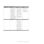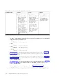
b)
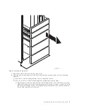
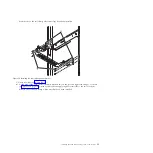
Mark the top mounting hole of the lowest EIA unit. Count up two holes and place another
mark beside that mounting hole. Mark the rack so that these marks can also be seen from
the rear of the rack. You now have two
(B)
marks on the rack, with one mounting hole
between the marks.
c)
Repeat the last two steps to place three marks on the corresponding mounting holes on the
front-right side of the rack.
d)
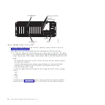
Go to the rear of the rack. On the left side, find the EIA unit that corresponds to the lowest
EIA unit marked on the front of the rack.
e)
Mark the top mounting hole of this EIA unit. Count up two holes and place another mark
beside that mounting hole. You now have two
(C)
marks on the rack, with one mounting
hole between the marks.
f)
Count up one mounting hole from where you placed your last mark, and place another
mark next to that mounting hole. Then count up three holes and place another mark beside
that mounting hole. Then count up two holes and place another mark beside that mounting
hole. You now have three
(D)
marks on the rack.
g)
Repeat the last two steps to place five marks on the corresponding mounting holes on the
rear-right side of the rack.
6.
Install the rail assembly into the rack as follows:
Important:
To complete this procedure, use two people to attach the rail assembly to the rack.
Position one person in front of the rack and one person at the rear of the rack.
CAUTION:
Installing the rails in the rack is a complex procedure. To install the rails correctly, you must
complete each task in the following order. Failure to do so might cause rail failure and potential
danger to yourself and the system unit.
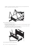
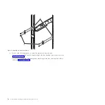
a.
Rotate down the front and back clamps
(C)
on the left and right rails, as shown in the following
figure.
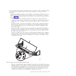
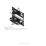
b.
On each rail, remove the tape holding the spring
(B)
to the rail. Hook the end of the spring
around the circular standoff on the rail.
c.
Start at the front of the rack. Extend the right rail and insert the rail pins
(D)
into the two lowest
mounting holes marked on the rack so that the rail is facing upward. Rotate up the front clamp
(C)
to secure the rail in place.
Notes:
v
If your rack has the square mounting holes, remove the rail pins
(D)
from the rail. Install the
larger rail pins provided with the rack installation kit.
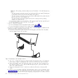
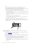
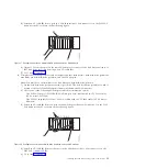
Figure 3. Marking the installation locations
6
Power Systems: Installing the 5802 and 5877 expansion units
Summary of Contents for Power System 5802
Page 1: ...Power Systems Installing the 5802 and 5877 expansion units GI11 4307 09...
Page 2: ......
Page 3: ...Power Systems Installing the 5802 and 5877 expansion units GI11 4307 09...
Page 6: ...iv Power Systems Installing the 5802 and 5877 expansion units...
Page 38: ...26 Power Systems Installing the 5802 and 5877 expansion units...
Page 52: ...40 Power Systems Installing the 5802 and 5877 expansion units...
Page 62: ...50 Power Systems Installing the 5802 and 5877 expansion units...
Page 63: ......
Page 64: ...Part Number 00L5079 Printed in USA GI11 4307 09 1P P N 00L5079...


