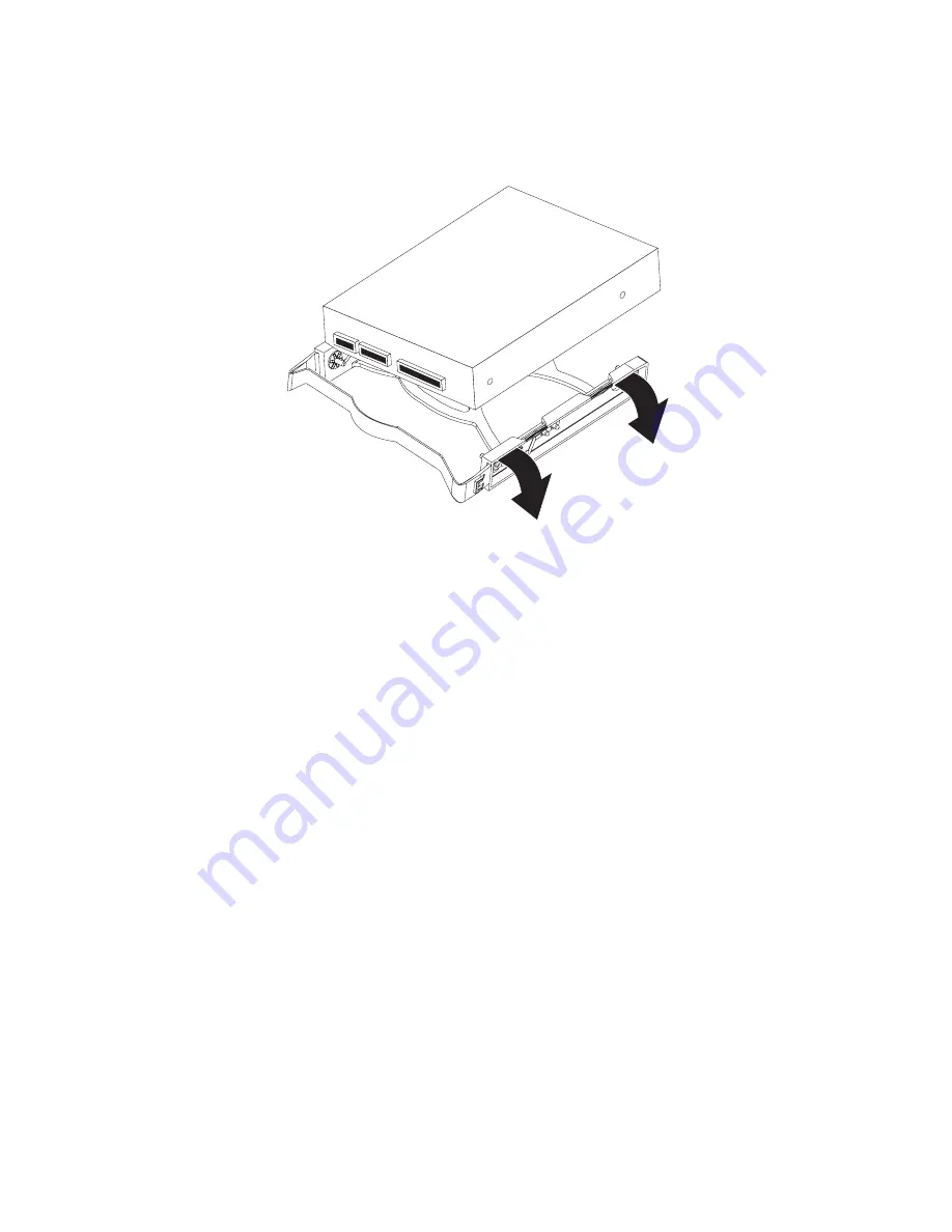
8.
Attach
the
new
drive
to
the
drive
tray.
Place
the
drive
on
the
drive
tray
and
align
the
holes
on
the
drive
with
the
mounting
pins
on
the
drive
tray.
Gently
pull
both
sides
of
the
drive
tray
outward
and
insert
the
mounting
pins
into
the
holes
on
the
drive.
9.
Align
the
drive
assembly
with
the
guide
rails
in
the
bay
(make
sure
that
the
connector
end
of
the
drive
is
facing
you).
10.
Determine
whether
the
new
drive
is
a
SATA
or
SCSI
device;
then,
connect
one
end
of
the
applicable
signal
cable
into
the
back
of
the
drive
and
the
other
end
of
this
cable
into
the
applicable
SATA
or
mini-PCI
SCSI
connector.
See
“Power
and
signal
cables
for
internal
drives”
on
page
53
for
additional
information
about
cabling
drives
and
“System
board
option
connectors”
on
page
77
for
the
location
of
SATA
and
mini-PCI
SCSI
connectors
on
the
system
board.
If
there
are
open
connectors
on
the
cables
that
connect
existing
SATA
or
SCSI
drives,
these
cables
can
be
used
to
connect
the
new
drive.
11.
Route
the
signal
cable
so
that
it
does
not
block
the
airflow
to
the
rear
of
the
drives
or
over
the
microprocessor.
12.
Route
the
signal
cable
so
that
it
does
not
block
the
airflow
to
the
rear
of
the
drives
or
over
the
microprocessor.
13.
Connect
the
power
cable
to
the
back
of
the
drive.
The
connectors
are
keyed
and
can
be
inserted
only
one
way.
14.
Push
the
drive-cage
retention
latch
toward
the
front
of
the
computer;
then,
rotate
the
drive
cage
back
into
the
computer.
Note:
As
you
rotate
the
drive
cage,
make
sure
the
hard
disk
drive
cables
or
other
internal
cables
do
not
impede
the
rotation
of
the
drive
cage.
15.
If
you
have
other
options
to
install
or
remove,
do
so
now.
52
IntelliStation
M
Pro
Types
6225
and
6228:
Hardware
Maintenance
Manual
and
Troubleshooting
Guide
Summary of Contents for IntelliStation M Pro 6225
Page 1: ...IntelliStation M Pro Types 6225 and 6228 Hardware Maintenance Manual and Troubleshooting Guide...
Page 2: ......
Page 3: ...IntelliStation M Pro Types 6225 and 6228 Hardware Maintenance Manual and Troubleshooting Guide...
Page 135: ...Appendix B Safety information 125...
Page 137: ...Appendix B Safety information 127...
Page 139: ...Appendix B Safety information 129...
Page 141: ...Appendix B Safety information 131...
Page 151: ...Appendix B Safety information 141...
Page 153: ...Appendix B Safety information 143...
Page 155: ...Appendix B Safety information 145...
Page 175: ......
Page 176: ...Part Number 25K8120 Printed in USA 1P P N 25K8120...


