background image

Statement


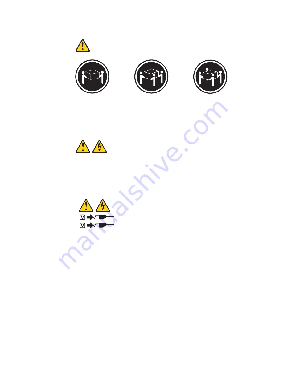
4:


18


kg


(39.7


lb)


32


kg


(70.5


lb)


55


kg


(121.2


lb)


CAUTION:


Use


safe


practices


when


lifting.


Statement


5:


CAUTION:


The


power


control


button


on


the


device


and


the


power


switch


on


the


power


supply


do


not


turn


off


the


electrical


current


supplied


to


the


device.


The


device


also


might


have


more


than


one


power


cord.


To


remove


all


electrical


current


from


the


device,


ensure


that


all


power


cords


are


disconnected


from


the


power


source.

1

2


viii


xSeries


100


Type


8486:


Installation


Guide

Summary of Contents for E Server x 100 Series

Page 1: ...ge Cable the server and options Start the server Install options Drives Microprocessors Adapters Memory Did the server start correctly Yes No Use ServerGuide to setup and configure hardware Did config...

Page 2: ...connections and verify that all optional devices you installed are on the ServerProven list You can view the ServerProven list at http www ibm com pc compat Server working properly Problem solved Pro...

Page 3: ...xSeries 100 Type 8486 Installation Guide ERserver...

Page 4: ...1 and the Warranty and Support Information document on the IBM IntelliStation Documentation CD First Edition October 2005 Copyright International Business Machines Corporation 2005 All rights reserved...

Page 5: ...r 23 Installing a security rope clip 24 Completing the installation 25 Installing the bezel 25 Installing the side cover 25 Connecting the cables 27 Updating the server configuration 27 Chapter 3 Serv...

Page 6: ...the documentation 59 Getting help and information from the World Wide Web 59 Software service and support 60 Hardware service and support 60 Appendix B Notices 61 Edition notice 61 Trademarks 62 Impor...

Page 7: ...alleert eerst de veiligheidsvoorschriften Ennen kuin asennat t m n tuotteen lue turvaohjeet kohdasta Safety Information Avant d installer ce produit lisez les consignes de s curit Vor der Installation...

Page 8: ...r disconnect signal cables v Never turn on any equipment when there is evidence of fire water or structural damage v Disconnect the attached power cords telecommunications systems networks and modems...

Page 9: ...es or regulations Statement 3 CAUTION When laser products such as CD ROMs DVD drives fiber optic devices or transmitters are installed note the following v Do not remove the covers Removing the covers...

Page 10: ...on on the device and the power switch on the power supply do not turn off the electrical current supplied to the device The device also might have more than one power cord To remove all electrical cur...

Page 11: ...ect a problem with one of these parts contact a service technician Statement 12 CAUTION The following label indicates a hot surface nearby Statement 13 DANGER Overloading a branch circuit is potential...

Page 12: ...n causante de cancer y de defectos cong nitos adem s de otros riesgos reproductivos L vese las manos despu s de usar el producto Important All caution and danger statements in this documentation begin...

Page 13: ...ollowing steps Note Changes are made periodically to the IBM Web site The actual procedure might vary slightly from what is described in this document 1 See http www ibm com support 2 Under Search tec...

Page 14: ...nd serial number Important The server keys cannot be duplicated by a locksmith If you lose them order replacement keys from the key manufacturer The key serial number and the telephone number of the m...

Page 15: ...ion Browser v If Autostart is enabled insert the CD into the CD or DVD drive The Documentation Browser starts automatically v If Autostart is disabled or is not enabled for all users use one of the fo...

Page 16: ...e notices provide important tips guidance or advice v Important These notices provide information or advice that might help you avoid inconvenient or problem situations v Attention These notices indic...

Page 17: ...em board with RJ 45 Ethernet port v Two serial ports v One parallel port v Two port Serial ATA controller v Four Universal Serial Bus USB v2 0 ports two on front and two on rear v Keyboard port v Mous...

Page 18: ...in the server open or close a latch and so on The following illustration shows the major components in the server Note The illustrations in this document might differ slightly from your hardware Cover...

Page 19: ...ift by standing or by pushing up with your leg muscles v Make sure that you have an adequate number of properly grounded electrical outlets for the server monitor and other devices v Back up all impor...

Page 20: ...nstall them To reduce the possibility of damage from electrostatic discharge observe the following precautions v Limit your movement Movement can cause static electricity to build up around you v The...

Page 21: ...r on its side 4 Remove the two thumbscrews from the rear of the server that secures the cover to the chassis Slide the cover slightly toward the rear of the chassis and lift it off the server and set...

Page 22: ...ide cover on page 9 2 From inside the server locate the two bezel release tabs at the bottom of the bezel Bezel release tabs 3 Press up slightly on both bezel release tabs while pulling the bottom of...

Page 23: ...M 1 memory connector If the server has one DIMM installed when you install an additional DIMM it must be installed in the DIMM 3 connector and it must be the same size speed type and technology as the...

Page 24: ...MMs in the sequence shown in the following table DIMM 4 DIMM 3 DIMM 2 DIMM 1 DIMM 1 error LED DIMM 2 error LED DIMM 3 error LED DIMM 4 error LED Memory installation sequence DIMMs Slots 1 DIMM 1 2 DIM...

Page 25: ...the connector by aligning the edges of the DIMM with the slots at the ends of the DIMM connector Firmly press the DIMM straight down into the connector by applying pressure on both ends of the DIMM s...

Page 26: ...mes with the drive v The server supports a maximum of two hard disk drives four DIMMs and one 5 25 inch device or one hard disk drive four DIMMs and two 5 25 inch devices or two hard disk drives two D...

Page 27: ...ng steps 1 Read the safety information that begins on page v and Installation guidelines on page 7 2 Turn off the server and peripheral devices and disconnect the power cords and all external cables 3...

Page 28: ...Drive retainer clip EMC shield Filler panel Note If you are installing a drive that contains a laser observe the following safety precaution 16 xSeries 100 Type 8486 Installation Guide...

Page 29: ...rom the package and place it on a static protective surface 7 Set any jumpers or switches on the drive according to the documentation that comes with the drive 8 Remove the drive retainer clip located...

Page 30: ...ch Serial ATA drive comes with a cable If you install an additional Serial ATA drive you will need an additional cable If you install the optional ServeRAID 7t S ATA controller all SATA drives must be...

Page 31: ...ll go 9 Attach the hard disk drive to the drive cage with the four screws 10 Connect one end of the signal cable into the back of the drive and make sure that the other end of the cable is connected i...

Page 32: ...ibbon cables that connect parallel IDE Serial ATA SCSI and diskette drives to the system board Two or three types of signal cables come with the server IDE The wider IDE signal cable has three connect...

Page 33: ...r the server see http www ibm com support To install an adapter complete the following steps 1 Read the safety information that begins on page v and Installation guidelines on page 7 2 Turn off the se...

Page 34: ...from the expansion slot earlier to secure the adapter to the chassis 9 Connect required cables to the adapter Route cables so that they do not block the flow of air from the fans If you are installing...

Page 35: ...additional information about SCSI adapters Note An optional SCSI adapter or cable option is required to connect external SCSI devices To cable an optional SCSI adapter complete the following steps 1 I...

Page 36: ...e following steps 1 Turn off the server and all attached devices Disconnect all external cables and power cords then remove the side cover See Removing the side cover on page 9 2 Use a screwdriver to...

Page 37: ...ottom of the bezel toward the server until the bezel snaps into place Installing the side cover Note You might find it easier to lay the server on its side to replace the side cover To replace the sid...

Page 38: ...Thumbscrews 3 Use the two thumbscrews that you removed earlier to secure the cover to the server chassis 26 xSeries 100 Type 8486 Installation Guide...

Page 39: ...rnal SCSI device you might receive a message that the configuration has changed The Configuration Setup Utility program starts automatically so that you can save the new configuration settings See Cha...

Page 40: ...28 xSeries 100 Type 8486 Installation Guide...

Page 41: ...D is lit it indicates that the CD or DVD drive is in use USB connectors Connect a USB device to these connectors System error LED When this LED is lit it indicates that a system error has occurred A L...

Page 42: ...s turned on When this LED is off it indicates that ac power is not present or the power supply or the LED itself has failed Note If this LED is off it does not mean that there is no electrical power i...

Page 43: ...server is connected to an ac power source Mouse connector Connect a mouse or other PS 2 device to this connector Keyboard connector Connect a PS 2 keyboard to this connector Serial 1 connector Connect...

Page 44: ...to power You can turn on the server and start the operating system by pressing the power control button The server can also be turned on in any of the following ways v If a power failure occurs while...

Page 45: ...ting system supports this feature After an orderly shutdown of the operating system the server will be turned off automatically v You can press the power control button to start an orderly shutdown of...

Page 46: ...34 xSeries 100 Type 8486 Installation Guide...

Page 47: ...install the operating system For information about the supported operating system versions see the label on the CD If the ServerGuide Setup and Installation CD did not come with your server you can do...

Page 48: ...am Enabling the Broadcom NetXtreme Gigabit Ethernet Boot Agent The Broadcom NetXtreme Gigabit Ethernet Boot Agent is part of the BIOS You can use it to configure the network as a startable device and...

Page 49: ...te and mode You do not have to set any jumpers or configure the controller However you must install a device driver when you install a different operating system to enable the operating system to addr...

Page 50: ...38 xSeries 100 Type 8486 Installation Guide...

Page 51: ...onfiguration problem See POST beep codes in the Problem Determination and Service Guide on the IBM xSeries Documentation CD for more information v ServerGuide problems This table lists problem symptom...

Page 52: ...llow the suggested actions in the order in which they are listed in the Action column until the problem is solved v See the parts listing in the Problem Determination and Service Guide to determine wh...

Page 53: ...e a Battery b Failing device if the device is a FRU then the device should be replaced by a trained service technician only c Trained service technician only System board 163 A real time clock error o...

Page 54: ...ontroller error occurred 1 If you have installed a USB keyboard run the Configuration Setup Utility program and enable keyboardless operation to prevent this error message from being displayed during...

Page 55: ...ll other adapters in the Configuration Setup Utility program are correct If the memory resource settings are not correct change them 3 If all memory resources are being used remove an adapter to make...

Page 56: ...wing components one at a time in the order shown restarting the server each time a Trained service technician only Microprocessor b Trained service technician only System board 00019701 Processor fail...

Page 57: ...05 An operating system was not found 1 Make sure that a bootable operating system is installed 2 Run the hard disk drive diagnostic tests see the Problem Determination and Service Guide for informatio...

Page 58: ...nstalled v Make sure that there are no duplicate SCSI IDs or IRQ assignments v Make sure that the hard disk drive is connected correctly The operating system Installation program continuously loops Ma...

Page 59: ...lumn until the problem is solved v See the parts listing in Problem Determination and Service Guide to determine which components are customer replaceable units CRU and which components are field repl...

Page 60: ...ation 2 To prevent diskette drive read write errors make sure that the distance between monitors and diskette drives is at least 76 mm 3 in 3 Run the diskette drive diagnostic test 4 Reseat the follow...

Page 61: ...Reseat all hard disk drives and cables then run the hard disk drive diagnostic tests again A hard disk drive passes the diagnostic Fixed Disk Test but the problem remains Run the diagnostic SCSI Fixed...

Page 62: ...keyboard cable is securely connected to the computer and the keyboard and mouse cables are not reversed v The computer and the monitor are turned on 2 Replace the following components one at a time in...

Page 63: ...sage 289 v If the DIMM was disabled by a system management interrupt SMI replace the DIMM v If the DIMM was disabled by the user or by POST run the Configuration Setup Utility program and enable the D...

Page 64: ...d c Trained service technician only System board Only the cursor appears See Solving undetermined problems in the Problem Determination and Service Guide The monitor works when you turn on the compute...

Page 65: ...step must be performed only by a trained service technician Symptom Action An IBM optional device that was just installed does not work 1 Make sure that v The device is designed for the computer see...

Page 66: ...ted to the computer and to a working electrical outlet v The type of memory that is installed is correct 2 If you just installed an optional device remove it and restart the computer If the computer n...

Page 67: ...the Action column until the problem is solved v See the parts listing in Problem Determination and Service Guide to determine which components are customer replaceable units CRU and which components a...

Page 68: ...messages when using the software program see the information that comes with the software for a description of the messages and suggested solutions to the problem 3 Contact the place where you purchas...

Page 69: ...mination and Service Guide on the IBM xSeries Documentation CD for additional information Recovering from a BIOS update failure If power to the server is interrupted while BIOS code is being updated f...

Page 70: ...n download a file to create this diskette from http www ibm com support 10 Turn on the computer and the monitor 11 After the update is completed turn off the server and monitor 12 Remove the diskette...

Page 71: ...escribes the diagnostic tests that you can perform Most xSeries and IntelliStation systems operating systems and programs come with information that contains troubleshooting procedures and explanation...

Page 72: ...services go to http www ibm com services or go to http www ibm com planetwide for support telephone numbers In the U S and Canada call 1 800 IBM SERV 1 800 426 7378 Hardware service and support You c...

Page 73: ...TY OF ANY KIND EITHER EXPRESS OR IMPLIED INCLUDING BUT NOT LIMITED TO THE IMPLIED WARRANTIES OF NON INFRINGEMENT MERCHANTABILITY OR FITNESS FOR A PARTICULAR PURPOSE Some states do not allow disclaimer...

Page 74: ...s and Windows NT are trademarks of Microsoft Corporation in the United States other countries or both UNIX is a registered trademark of The Open Group in the United States and other countries Java and...

Page 75: ...ular purpose These products are offered and warranted solely by third parties IBM makes no representations or warranties with respect to non IBM products Support if any for the non IBM products is pro...

Page 76: ...enne et la Norv ge L etiquette du syst me respecte la Directive europ enne 2002 96 EC en mati re de D chets des Equipements Electriques et Electroniques DEEE qui d termine les dispositions de retour e...

Page 77: ...tteries Electronic emission notices IBM Eserver xSeries 100 Type 8486 Federal Communications Commission FCC statement Note This equipment has been tested and found to comply with the limits for a Clas...

Page 78: ...HOME OR OFFICE USE Industry Canada Class B emission compliance statement This Class B digital apparatus complies with Canadian ICES 003 Avis de conformit la r glementation d Industrie Canada Cet appa...

Page 79: ...IBM power cord part number Used in these countries and regions 02K0546 China 13F9940 Australia Fiji Kiribati Nauru New Zealand Papua New Guinea 13F9979 Afghanistan Albania Algeria Andorra Angola Armen...

Page 80: ...elize Bermuda Bolivia Brazil Caicos Islands Canada Cayman Islands Costa Rica Colombia Cuba Dominican Republic Ecuador El Salvador Guam Guatemala Haiti Honduras Jamaica Japan Mexico Micronesia Federal...

Page 81: ...onfiguring your server 35 controller SCSI 23 controls 29 controls and indicators 29 cooling 5 cover replacing 25 D danger statements 4 diagnostic tools 39 DIMM connector installing memory 12 locations...

Page 82: ...OST beep codes 40 error codes 40 power problems 54 power control button 30 power cords 67 power supply specifications 5 power switch 30 power cord connector 31 power on LED 30 power on self test POST...

Page 83: ...EDs 57 system error LED 29 system reliability 7 T tape drive installing 14 trademarks 62 troubleshooting tables 47 U United States electronic emission Class B notice 65 United States FCC Class B notic...

Page 84: ...72 xSeries 100 Type 8486 Installation Guide...

Page 85: ......

Page 86: ...Part Number 31R2068 Printed in USA 1P P N 31R2068...

Reviews: