


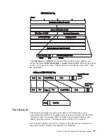


Packet forwarding
The switch uses a forwarding table to store the information that it collects. The
switch programs the mapping from the destination MAC address to the destination
port number into its forwarding table. This information is then used to forward
packets. This reduces the traffic congestion on the network, because packets,
instead of being transmitted to all ports, are transmitted to the destination port only.
For example, if port 1 receives a packet destined for a station on port 2, the switch
transmits that packet through port 2 only and transmits nothing through the other
ports. This process is referred to as learning the network topology.
The aging time affects the learning process of the switch. Dynamic forwarding table
entries, which consist of the source and destination MAC addresses and their
associated port numbers, are deleted from the table if they are not accessed within
the aging time.
The aging time can be from 17.2 to 2200 seconds with a default value of 300
seconds. A very long aging time can result in dynamic forwarding table entries that
are out of date or no longer exist. This might cause the switch to make incorrect
packet-forwarding decisions.
If the aging time is too short, however, many entries might be aged out too soon.
This will result in a high percentage of received packets whose source addresses
cannot be found in the forwarding table. In this case, the switch will broadcast the
packet to all ports, thus negating many of the benefits of having a switch.
Static forwarding entries are not affected by the aging time.
Spanning Tree Protocol
The Institute of Electrical and Electronics Engineers (IEEE) 802.1D Spanning Tree
Protocol (STP) enables the blocking of links between switches that form loops
within the network. When multiple links between switches are detected, a primary
link is established. Duplicated links are blocked from use and become standby links.
The protocol enables the duplicate links to be used in the event of a failure of the
primary link. When the STP is configured and enabled, primary links are
established, and duplicated links are blocked automatically. The reactivation of the
blocked links (at the time of a primary link failure) is also accomplished
automatically, without operator intervention.
This automatic network reconfiguration provides maximum uptime to network users.
However, the concepts of the STA and protocol are a complicated and complex
subject and must be fully researched and understood. It is possible to cause
serious degradation of the performance of the network if the spanning tree is
incorrectly configured. Read the following information before making any changes
from the default values.
The switch STP performs the following functions:
v
Creates a single spanning tree from any combination of switching or bridging
elements
v
Automatically reconfigures the spanning tree to compensate for the failure,
addition, or removal of any element in the tree
v
Reconfigures the spanning tree without operator intervention
Chapter 4. Switch management and operating concepts
23
Summary of Contents for BladeCenter Management Module
Page 1: ...IBM BladeCenter 4 Port Gb Ethernet Switch Module Installation and User s Guide ERserver ...
Page 2: ......
Page 3: ...IBM BladeCenter 4 Port Gb Ethernet Switch Module Installation and User s Guide ERserver ...
Page 9: ...Japanese Voluntary Control Council for Interference VCCI statement 159 Index 161 Contents vii ...
Page 10: ...viii IBM BladeCenter 4 Port Gb Ethernet Switch Module Installation and User s Guide ...
Page 18: ...xvi IBM BladeCenter 4 Port Gb Ethernet Switch Module Installation and User s Guide ...
Page 32: ...14 IBM BladeCenter 4 Port Gb Ethernet Switch Module Installation and User s Guide ...
Page 92: ...74 IBM BladeCenter 4 Port Gb Ethernet Switch Module Installation and User s Guide ...
Page 134: ...116 IBM BladeCenter 4 Port Gb Ethernet Switch Module Installation and User s Guide ...
Page 136: ...118 IBM BladeCenter 4 Port Gb Ethernet Switch Module Installation and User s Guide ...
Page 138: ...120 IBM BladeCenter 4 Port Gb Ethernet Switch Module Installation and User s Guide ...
Page 155: ...Appendix D Understanding and troubleshooting the Spanning Tree Protocol 137 ...
Page 158: ...140 IBM BladeCenter 4 Port Gb Ethernet Switch Module Installation and User s Guide ...
Page 172: ...154 IBM BladeCenter 4 Port Gb Ethernet Switch Module Installation and User s Guide ...
Page 177: ...Japanese Voluntary Control Council for Interference VCCI statement Appendix G Notices 159 ...
Page 178: ...160 IBM BladeCenter 4 Port Gb Ethernet Switch Module Installation and User s Guide ...
Page 183: ......
Page 184: ... Part Number 59P6530 Printed in U S A 1P P N 59P6530 ...


