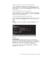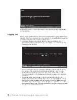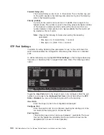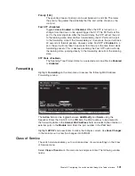
To set a port as either a tagged or an untagged port, highlight the first field of
Tagging (U/T)
field. The state of each port can be set by highlighting the port entry
using the arrow keys and then toggling between
U
or
T
using the Spacebar.
U
Specifies the port as an Untagged member of the VLAN. When an
untagged packet is transmitted by the port, the packet header remains
unchanged. When a tagged packet exits the port, the tag is stripped and
the packet is changed to an untagged packet.
T
Specifies the port as a Tagged member of the VLAN. When an untagged
packet is transmitted by the port, the packet header is changed to include
the 32-bit tag associated with the Port VLAN Identifier (PVID); see
“Configure 802.1Q Port Settings”). When a tagged packet exits the port, the
packet header is unchanged.
If the port is attached to a device that is not IEEE 802.1Q VLAN compliant
(VLAN-tag unaware), then the port should be set to
U
- Untagged.
If the port is attached to a device that is IEEE 802.1Q VLAN compliant, (VLAN-tag
aware), then the port should be set to
T
- Tagged.
Press
APPLY
to make the changes effective for the current session. To enter the
changes into NVRAM, highlight
Save Changes
in the main menu and press Enter.
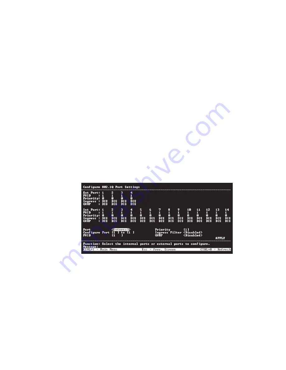
Configure 802.1Q Port Settings
To configure an 802.1Q VLAN, highlight
Configure 802.1Q Port Settings
on the
VLAN Menu and press Enter:
To assign a port a Port VLAN Identifier (PVID), select the desired module and
port(s) in the first two fields, and enter the PVID for the VLAN member ports that
you want to configure in the third field.
PVID is a classification mechanism that associates a port with a specific VLAN and
is used to make forwarding decisions for untagged packets received by the port.
For example, if port #2 is assigned a PVID of 3, then all untagged packets received
on port #2 will be assigned to VLAN 3. This number is generally the same as the
VID# number assigned to the port in the
Edit 802.1Q VLANs
window shown in
“Edit 802.1Q VLANs” on page 107.
To set the priority of a port, select the desired module and port(s) in the first two
fields and then enter the desired priority value in the
Priority
field.
Chapter 6. Configuring the switch module through the Telnet interface
109
Summary of Contents for BladeCenter Management Module
Page 1: ...IBM BladeCenter 4 Port Gb Ethernet Switch Module Installation and User s Guide ERserver ...
Page 2: ......
Page 3: ...IBM BladeCenter 4 Port Gb Ethernet Switch Module Installation and User s Guide ERserver ...
Page 9: ...Japanese Voluntary Control Council for Interference VCCI statement 159 Index 161 Contents vii ...
Page 10: ...viii IBM BladeCenter 4 Port Gb Ethernet Switch Module Installation and User s Guide ...
Page 18: ...xvi IBM BladeCenter 4 Port Gb Ethernet Switch Module Installation and User s Guide ...
Page 32: ...14 IBM BladeCenter 4 Port Gb Ethernet Switch Module Installation and User s Guide ...
Page 92: ...74 IBM BladeCenter 4 Port Gb Ethernet Switch Module Installation and User s Guide ...
Page 134: ...116 IBM BladeCenter 4 Port Gb Ethernet Switch Module Installation and User s Guide ...
Page 136: ...118 IBM BladeCenter 4 Port Gb Ethernet Switch Module Installation and User s Guide ...
Page 138: ...120 IBM BladeCenter 4 Port Gb Ethernet Switch Module Installation and User s Guide ...
Page 155: ...Appendix D Understanding and troubleshooting the Spanning Tree Protocol 137 ...
Page 158: ...140 IBM BladeCenter 4 Port Gb Ethernet Switch Module Installation and User s Guide ...
Page 172: ...154 IBM BladeCenter 4 Port Gb Ethernet Switch Module Installation and User s Guide ...
Page 177: ...Japanese Voluntary Control Council for Interference VCCI statement Appendix G Notices 159 ...
Page 178: ...160 IBM BladeCenter 4 Port Gb Ethernet Switch Module Installation and User s Guide ...
Page 183: ......
Page 184: ... Part Number 59P6530 Printed in U S A 1P P N 59P6530 ...

