• Before you open the device covers, unless instructed otherwise in the installation and
configuration procedures: Disconnect the attached AC power cords, turn off the applicable
circuit breakers located in the rack power distribution panel (PDP), and disconnect any
telecommunications systems, networks, and modems.
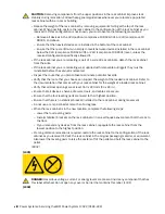
DANGER:
• Connect and disconnect cables as described in the following procedures when installing,
moving, or opening covers on this product or attached devices.
To Disconnect:
1. Turn off everything (unless instructed otherwise).
2. For AC power, remove the power cords from the outlets.
3. For racks with a DC power distribution panel (PDP), turn off the circuit breakers located in the
PDP and remove the power from the Customer's DC power source.
4. Remove the signal cables from the connectors.
5. Remove all cables from the devices.
To Connect:
1. Turn off everything (unless instructed otherwise).
2. Attach all cables to the devices.
3. Attach the signal cables to the connectors.
4. For AC power, attach the power cords to the outlets.
5. For racks with a DC power distribution panel (PDP), restore the power from the Customer's
DC power source and turn on the circuit breakers located in the PDP.
6. Turn on the devices.
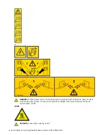
Sharp edges, corners and joints may be present in and around the system. Use care when
handling equipment to avoid cuts, scrapes and pinching. (D005)
Attention:
Failure to follow the step-by-step sequence for part removal or installation might result in part or
system damage.
For safety, airflow purposes and thermal performance, the service access cover must be installed
and fully seated before you power the system on.
For safety and airflow purposes and thermal performance, if you remove parts from the system,
you must ensure that PCIe tailstock fillers are present.
Use the following precautions whenever you handle electronic components or cables.
• The electrostatic discharge (ESD) kit and the ESD wrist strap must be used when you handle
logic cards, single chip modules, multi-chip modules, electronic boards, and disk drives.
• Keep all electronic components in the shipping container or envelope until you are ready to
install them.
• If you remove, and then reinstall an electronic component, temporarily place the component on
an ESD pad or blanket.
Removing and replacing drive backplanes in the 9183-22X system
Find information about removing and replacing drive backplanes in the IBM Power System IC922
(9183-22X) server.
2 Power Systems: Servicing the IBM Power System IC922 (9183-22X)


