background image

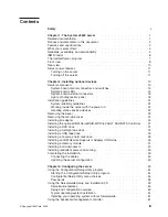
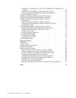
Enabling


and


configuring


SOL


using


the


OSA


SMBridge


management


utility


program


.


.


.


.


.


.


.


.


.


.


.


.


.


.


.


.


.


.


.


.


.


.


.


.


. 62


Installing


the


OSA


SMBridge


management


utility


program


.


.


.


.


.


.


.


. 70


Using


the


baseboard


management


controller


utility


programs


.


.


.


.


.


.


. 72


Using


the


Boot


Menu


program


.


.


.


.


.


.


.


.


.


.


.


.


.


.


.


.


.


.


. 73


Enabling


the


Broadcom


Gigabit


Ethernet


Utility


program


.


.


.


.


.


.


.


.


.


. 73


Configuring


the


Broadcom


Gigabit


Ethernet


controller


.


.


.


.


.


.


.


.


.


.


. 74


Setting


up


the


Remote


Supervisor


Adapter


II


SlimLine


.


.


.


.


.


.


.


.


.


. 74


Requirements


.


.


.


.


.


.


.


.


.


.


.


.


.


.


.


.


.


.


.


.


.


.


.


. 74


Cabling


the


Remote


Supervisor


Adapter


II


SlimLine


.


.


.


.


.


.


.


.


.


. 75


Installing


the


Remote


Supervisor


Adapter


II


SlimLine


firmware


.


.


.


.


.


. 75


Completing


the


setup


.


.


.


.


.


.


.


.


.


.


.


.


.


.


.


.


.


.


.


.


. 76


Using


the


Adaptec


RAID


Configuration


Utility


program


.


.


.


.


.


.


.


.


.


. 76


Starting


the


Adaptec


RAID


Configuration


Utility


program


.


.


.


.


.


.


.


.


. 76


Adaptec


RAID


Configuration


Utility


menu


choices


.


.


.


.


.


.


.


.


.


.


. 77


Creating


a


RAID


array


.


.


.


.


.


.


.


.


.


.


.


.


.


.


.


.


.


.


.


.


. 77


Viewing


the


array


configuration


.


.


.


.


.


.


.


.


.


.


.


.


.


.


.


.


.


. 77


Using


ServeRAID


Manager


.


.


.


.


.


.


.


.


.


.


.


.


.


.


.


.


.


.


.


. 77


Configuring


the


controller


.


.


.


.


.


.


.


.


.


.


.


.


.


.


.


.


.


.


.


. 78


Viewing


the


configuration


.


.


.


.


.


.


.


.


.


.


.


.


.


.


.


.


.


.


.


. 79


Updating


IBM


Director


.


.


.


.


.


.


.


.


.


.


.


.


.


.


.


.


.


.


.


.


.


. 79


Appendix.


Notices


.


.


.


.


.


.


.


.


.


.


.


.


.


.


.


.


.


.


.


.


.


.


. 81


Trademarks


.


.


.


.


.


.


.


.


.


.


.


.


.


.


.


.


.


.


.


.


.


.


.


.


.


. 81


Important


notes


.


.


.


.


.


.


.


.


.


.


.


.


.


.


.


.


.


.


.


.


.


.


.


.


. 82


Product


recycling


and


disposal


.


.


.


.


.


.


.


.


.


.


.


.


.


.


.


.


.


.


. 83


Battery


return


program


.


.


.


.


.


.


.


.


.


.


.


.


.


.


.


.


.


.


.


.


.


. 84


Electronic


emission


notices


.


.


.


.


.


.


.


.


.


.


.


.


.


.


.


.


.


.


.


. 85


Federal


Communications


Commission


(FCC)


statement


.


.


.


.


.


.


.


.


. 85


Industry


Canada


Class


A


emission


compliance


statement


.


.


.


.


.


.


.


. 86


Avis


de


conformité


à


la


réglementation


d’Industrie


Canada


.


.


.


.


.


.


.


. 86


Australia


and


New


Zealand


Class


A


statement


.


.


.


.


.


.


.


.


.


.


.


. 86


United


Kingdom


telecommunications


safety


requirement


.


.


.


.


.


.


.


.


. 86


European


Union


EMC


Directive


conformance


statement


.


.


.


.


.


.


.


.


. 86


Taiwanese


Class


A


warning


statement


.


.


.


.


.


.


.


.


.


.


.


.


.


.


. 87


Chinese


Class


A


warning


statement


.


.


.


.


.


.


.


.


.


.


.


.


.


.


.


. 87


Japanese


Voluntary


Control


Council


for


Interference


(VCCI)


statement


.


.


. 87


Index


.


.


.


.


.


.


.


.


.


.


.


.


.


.


.


.


.


.


.


.


.


.


.


.


.


.


.


. 89


iv


IBM


System


x3500


Type


7977:


User’s


Guide

Summary of Contents for 7977E7U

Page 1: ...IBM System x3500 Type 7977 User s Guide...

Page 2: ......

Page 3: ...IBM System x3500 Type 7977 User s Guide...

Page 4: ...n page 81 and the Warranty and Support Information document on the IBM System x Documentation CD Fifth Edition October 2008 Copyright International Business Machines Corporation 2008 US Government Use...

Page 5: ...Installing an adapter 24 Installing the optional IBM ServeRAID MR10is VAULT SAS SATA Controller 27 Installing a DVD drive 31 Installing a full high tape drive 32 Installing a USB tape drive 33 Install...

Page 6: ...ec RAID Configuration Utility menu choices 77 Creating a RAID array 77 Viewing the array configuration 77 Using ServeRAID Manager 77 Configuring the controller 78 Viewing the configuration 79 Updating...

Page 7: ...alleert eerst de veiligheidsvoorschriften Ennen kuin asennat t m n tuotteen lue turvaohjeet kohdasta Safety Information Avant d installer ce produit lisez les consignes de s curit Vor der Installation...

Page 8: ...h translated versions of the caution or danger statement in the IBM Safety Information book For example if a caution statement is labeled Statement 1 translations for that caution statement are in the...

Page 9: ...quipment when there is evidence of fire water or structural damage v Disconnect the attached power cords telecommunications systems networks and modems before you open the device covers unless instruc...

Page 10: ...a lithium battery replace it only with the same module type made by the same manufacturer The battery contains lithium and can explode if not properly used handled or disposed of Do not v Throw or im...

Page 11: ...he device v Use of controls or adjustments or performance of procedures other than those specified herein might result in hazardous radiation exposure DANGER Some laser products contain an embedded Cl...

Page 12: ...tton on the device and the power switch on the power supply do not turn off the electrical current supplied to the device The device also might have more than one power cord To remove all electrical c...

Page 13: ...parts inside these components If you suspect a problem with one of these parts contact a service technician Statement 11 CAUTION The following label indicates sharp edges corners or joints nearby Sta...

Page 14: ...xii IBM System x3500 Type 7977 User s Guide...

Page 15: ...s Guide contains general information about the server including how to install supported optional devices and how to configure the server The following documentation also comes with the server v Impor...

Page 16: ...ublications lookup 4 From the Product family menu select System x3500 and click Continue Notices and statements in this document The caution and danger statements that appear in this document are also...

Page 17: ...lb when fully configured or 20 kg 42 lb minimum Racks are marked in vertical increments of 4 45 cm 1 75 inches Each increment is referred to as a unit or U A 1 U high device is 4 45 cm 1 75 inches tal...

Page 18: ...k For more information see Configuring the Broadcom Gigabit Ethernet controller on page 74 v Intelligent Platform Management Interface IPMI 2 0 IPMI 2 0 support providing secure remote power on power...

Page 19: ...upports ServeRAID adapters to create redundant array of independent disks RAID configurations v Symmetric multiprocessing SMP The server supports up to two Intel Xeon dual core microprocessors If the...

Page 20: ...ages posted to the error log v Power on self test POST v Predictive Failure Analysis PFA alerts v Read only memory ROM checksums v Redundant Ethernet capabilities requires an optional Ethernet adapter...

Page 21: ...ools that are designed to reduce the total cost of managing and supporting networked systems By deploying IBM Director you can achieve reductions in ownership costs through the following benefits v Re...

Page 22: ...supply or the LED itself has failed A power LED is also on the rear of the server Power control button Press this button to turn the server on and off manually A power control button shield comes with...

Page 23: ...r is installed in the server and the LED flashes slowly one flash per second the drive is being rebuilt If the LED flashes rapidly three flashes per second the controller is identifying the drive Hard...

Page 24: ...nect a parallel device to this connector Video connector Connect a monitor to this connector USB 3 connector Connect a USB device to this connector Ethernet connector Use this connector to connect the...

Page 25: ...erver and start the operating system by pressing the power control button The server can also be turned on in any of the following ways v If a power failure occurs while the server is turned on the se...

Page 26: ...utomatically v You can press the power control button to start an orderly shutdown of the operating system and turn off the server if your operating system supports this feature v If the operating sys...

Page 27: ...nents in the server Bezel Control panel assembly USB cable assembly SAS backplane Fan assembly Hot swap fan Power supply Power supply filler Power supply cage Hard disk drive DVD drive Processor baffl...

Page 28: ...for information about the switch settings Wake on LAN CN 45 SW4 Boot block Clear CMOS Table 2 Switches on SW4 Switch number Description 1 Boot block v Leave the switch in the off position for normal m...

Page 29: ...Safety on page v Installation guidelines on page 21 and Handling static sensitive devices on page 22 2 Any system board switch or jumper blocks that are not shown in the illustrations in this documen...

Page 30: ...US FAN POWER SUPPLY PCI BUS 2 1 CONFIG TEMP REMIND SEE INSIDE COVER FOR MORE SERVICE INFORMATION Use the remind button on the light path diagnostic panel to acknowledge that an error has occurred with...

Page 31: ...LEDs 3 Reseat the following components a Power supply b Trained service technician only Power backplane 4 Replace the components listed in step 3 one at a time in the order shown restarting the server...

Page 32: ...service technician only Make sure that the microprocessors are installed in the correct sequence 1 Check the BMC log or the system error log to determine the reason for the lit LED 2 Find the failing...

Page 33: ...the DIMM 3 Replace the following components one at a time in the order shown restarting the server each time a DIMM b Trained service technician only System board DASD RAID A hard disk drive integrat...

Page 34: ...ly that step must be performed only by a trained service technician Lit light path diagnostics LED with the system error or information LED also lit Description Action NMI A hardware error has been re...

Page 35: ...you If you have to lift a heavy object observe the following precautions Make sure that you can stand safely without slipping Distribute the weight of the object equally between your feet Use a slow...

Page 36: ...cause the microprocessor to overheat v Microprocessor socket 2 always contains either a microprocessor duct or a microprocessor and heat sink Working inside the server with the power on The server sup...

Page 37: ...tatic electricity Removing the bezel Important Before you install optional hardware make sure that the server is working correctly Start the server and make sure that the operating system starts if an...

Page 38: ...nnect all external cables and power cords 4 Using the supplied key unlock the left side cover 5 Pull the cover release latch down and rotate the top edge of the cover away from the server Attention Fo...

Page 39: ...an install PCI adapters that do not support sharing of PCI interrupts v You can order an optional IBM ServeRAID MR10is VAULT SAS SATA Controller that supports RAID levels 0 1 5 6 10 50 and 60 You can...

Page 40: ...pter retention clip on the adapter support bracket Otherwise continue with the next step Adapter guide 7 Press the adapter firmly into the expansion slot lower the adapter retention latch and make sur...

Page 41: ...peripheral devices and disconnect the power cords and all external cables Attention To avoid breaking the retaining clips or damaging the ServeRAID MR10is SAS SATA adapter connector open and close the...

Page 42: ...ply Press down on the orange release lever and pull the power supply out of the bay using the handle b Lift up the power supply cage handle and pull the power supply cage assembly all the way up until...

Page 43: ...onnectors on the controller to which you connect the signal cables from the drive backplanes The following illustration shows which end of the cable connects to the backplane and to the controller Cha...

Page 44: ...and route the cable around the right side of the front fan cage assembly and along the chassis wall make sure that the cable is in front of the fan cage release tab then connect it to connector J8 on...

Page 45: ...eft side of the bezel away from the server then pull the bezel away from the server 5 Disconnect the DVD drive cable from the system board 6 Grasp the blue tabs on each side of the drive and press the...

Page 46: ...ezel retention tab at the center left edge of the bezel and rotate the left side of the bezel away from the server then pull the bezel away from the server 5 Connect the full high tape drive cable to...

Page 47: ...ft side cover on page 24 4 Remove the front fan cage assembly a Press the fan cage release latches on each side of the fan cage toward the sides of the server The cage will lift up slightly when the r...

Page 48: ...from top to bottom on models with eight hard disk drives and 0 through 11 from top to bottom on models with 12 hard disks v For a list of supported optional devices for the server see http www ibm com...

Page 49: ...drive is being accessed 2 If the server is configured for RAID operation using an optional ServeRAID adapter you might have to reconfigure your disk arrays after you install hard disk drives See the S...

Page 50: ...pter II SlimLine retention tab Remote Supervisor Adapter II SlimLine 5 Open the rear adapter retention bracket and install the Remote Supervisor Adapter II SlimLine retention tab on the bracket by cli...

Page 51: ...t If you have other optional devices to install or remove do so now Otherwise go to Completing the installation on page 49 Installing a memory module The following notes describe the types of dual inl...

Page 52: ...alled v The server supports memory mirroring mirroring mode and online spare memory Memory mirroring replicates and stores data on DIMMs within two branches simultaneously You must enable memory mirro...

Page 53: ...figuration Setup Utility program To enable online spare memory in the Configuration Setup Utility program select Devices and I O Ports Advanced Chipset Control Memory Branch Mode Use the arrow keys to...

Page 54: ...ted by using some or all of the chips on a DIMM For an ECC DIMM a memory rank is a block of 72 data bits 64 bits plus 8 ECC bits The minimum memory configuration is two single rank DIMMs that are inst...

Page 55: ...roring and non mirroring modes using identical single rank x8 technology or double rank x4 technology DIMMs The memory capacity is dependent on the size and technology of the DIMMs that you install Ta...

Page 56: ...upplies from the server 4 Raise the power supply cage out of the way a Press in on the power supply latch bracket which is on the left side of the server when you are facing the rear of the server b L...

Page 57: ...of the DIMM simultaneously The retaining clips snap into the locked position when the DIMM is firmly seated in the connector If there is a gap between the DIMM and the retaining clips the DIMM has no...

Page 58: ...from the fan cage a Grasp the two pinch points on the top of the air duct and squeeze them together b Lift the air duct up and out of the server and set it aside 4 Release the microprocessor retention...

Page 59: ...into the connector by applying pressure on both ends of the VRM simultaneously The retaining clips snap into the locked position when the VRM is seated in the connector 13 Reinstall the microprocessor...

Page 60: ...en push the baffle to the left and lift it out of the fan cage assembly 5 Install two hot swap fans in the empty bays of the fan cage assembly Release latch Power supply 6 Remove the power supply and...

Page 61: ...duct Plastic push pins Positioning pins Rivet Pin a Remove the four screws that secure the DIMM air baffle to the power supply cage b Push the DIMM air baffle toward the rear of the server until the p...

Page 62: ...er the power supply structure into position For clarity the power supply cage is not shown in the illustration Rear fan assembly with baffle 11 Install the rear fan and fan structure on the chassis a...

Page 63: ...that the dc power LED on the top of the power supply is lit also 17 Reconnect the external cables If you have other optional devices to install or remove do so now Otherwise go to Completing the insta...

Page 64: ...server Video Mouse Power cord Keyboard Serial 1 COM 1 Parallel Serial 2 COM 2 USB 4 Ethernet 10 100 1000 Ethernet 10 100 1000 RJ 45 USB 3 AC power LED DC power LED Updating the server configuration W...

Page 65: ...r information about reconfiguring the disk arrays If you have installed a Remote Supervisor Adapter II SlimLine to manage the server remotely see the Remote Supervisor Adapter User s Guide which comes...

Page 66: ...52 IBM System x3500 Type 7977 User s Guide...

Page 67: ...nce that is set in the Configuration Setup Utility program and temporarily assign a device to be first in the startup sequence see Using the Boot Menu program on page 73 v Broadcom Gigabit Ethernet Ut...

Page 68: ...you have set both a power on password and an administrator password you must type the administrator password to access the full Configuration Setup Utility menu If you do not type the administrator p...

Page 69: ...Port Setup Select this choice to enable or disable the parallel port and to adjust the parallel port resources and features Remote Console Redirection Select this choice to enable and configure seria...

Page 70: ...lures to find a boot record v Advanced Setup Select this choice to change settings for advanced hardware features Important The server might malfunction if these optional devices are incorrectly confi...

Page 71: ...Select this choice to change the serial port sharing and access mode v Serial Port Sharing Enable or disable serial port sharing Enabled is the default setting v Serial Port Access Mode Share disable...

Page 72: ...an administrator password for a system administrator you can type either password to complete the system startup A system administrator who types the administrator password has access to the full Con...

Page 73: ...s to the full Configuration Setup Utility menu You can use any combination of up to seven characters A Z a z and 0 9 for the password The Administrator Password choice is on the Configuration Setup Ut...

Page 74: ...S RAID configuration program v Checks the microcode firmware levels of a ServeRAID adapter and determines whether a later level is available from the CD v Detects installed optional hardware devices a...

Page 75: ...he latest operating system installation instructions from the IBM Web site Note Changes are made periodically to the IBM Web site The actual procedure might vary slightly from what is described in thi...

Page 76: ...load the latest version of the BMC firmware from http www ibm com systems support b Update the BMC firmware following the instructions that come with the update file that you downloaded 3 Configure th...

Page 77: ...during communication over a serial connection You must enable it when using a Linux operating system 1 Add the following line to the end of the Run gettys in standard runlevels section of the etc ini...

Page 78: ...this file after modification Original etc lilo conf contents prompt timeout 50 default linux boot dev hda map boot map install boot boot b message boot message linear image boot vmlinuz 2 4 9 e 12smp...

Page 79: ...Linux operating system starts a LILO boot prompt is displayed instead of the graphical user interface Press Tab at this prompt to install all of the boot options that are listed To load the operating...

Page 80: ...by anaconda Note that you do not have to rerun grub after making changes to this file NOTICE You have a boot partition This means that all kernel and initrd paths are relative to boot eg root hd0 0 ke...

Page 81: ...trd initrd 2 4 9 e 12 img You must restart the Linux operating system after you complete these procedures for the changes to take effect and to enable SOL SUSE SLES 8 0 configuration Note This procedu...

Page 82: ...white blue black light gray default 0 timeout 8 title linux kernel hd0 1 boot vmlinuz root dev hda2 acpi oldboot vga 791 1 initrd hd0 1 boot initrd title floppy root chainloader 1 title failsafe kern...

Page 83: ...rompt then press Enter to display the current boot options for your server b In the Boot Entries section locate the boot entry ID for the section with an OS friendly name of Windows Server 2003 Standa...

Page 84: ...sk 0 rdisk 0 partition 1 WINDOWS OS Load Options fastdetect redirect You must restart the Windows 2003 operating system after you complete this procedure for the changes to take effect and to enable S...

Page 85: ...cedures 1 Go to http www ibm com systems support download the utility program and create the OSA BMC Management Utility CD 2 Insert the OSA BMC Management Utility CD into the drive 3 Type mount mnt cd...

Page 86: ...board management controller firmware and SDR FRU data The firmware update utility updates the baseboard management controller firmware and SDR FRU data only and does not affect any device drivers Note...

Page 87: ...sysinfo Display system information that is related to the server and the globally unique identifier GUID Using the Boot Menu program The Boot Menu program is a built in menu driven configuration prog...

Page 88: ...lar links click Publications lookup 4 From the Product family menu select System x3500 and click Continue Setting up the Remote Supervisor Adapter II SlimLine You use the optional Remote Supervisor Ad...

Page 89: ...cable to the network Installing the Remote Supervisor Adapter II SlimLine firmware The software and firmware files that you need are contained in one system service package installation kit The kit co...

Page 90: ...Guide Using the Adaptec RAID Configuration Utility program Use the Adaptec RAID Configuration Utility programs to perform the following tasks v Configure a redundant array of independent disks RAID ar...

Page 91: ...in the array and press Enter 5 From the list of available RAID levels select the one that you want to use 6 Follow the instructions on the screen to complete the configuration then select Done to exi...

Page 92: ...ServeRAID Manager tree into an array and creating a RAID level 1 logical drive If you select custom configuration you can select the two physical drives that you want to group into an array and create...

Page 93: ...able updates and interim fixes complete the following steps Note Changes are made periodically to the IBM Web site The actual procedure might vary slightly from what is described in this document 1 Ch...

Page 94: ...80 IBM System x3500 Type 7977 User s Guide...

Page 95: ...LUDING BUT NOT LIMITED TO THE IMPLIED WARRANTIES OF NON INFRINGEMENT MERCHANTABILITY OR FITNESS FOR A PARTICULAR PURPOSE Some states do not allow disclaimer of express or implied warranties in certain...

Page 96: ...Inc in the United States and other countries Other company product or service names may be trademarks or service marks of others Important notes Processor speed indicates the internal clock speed of t...

Page 97: ...be found on IBM s Internet site at http www ibm com ibm environment products prp shtml Esta unidad debe reciclarse o desecharse de acuerdo con lo establecido en la normativa nacional o local aplicabl...

Page 98: ...ize any potential effects of EEE on the environment and human health due to the potential presence of hazardous substances in EEE For proper collection and treatment contact your local IBM representat...

Page 99: ...tery may also include a chemical symbol for the metal concerned in the battery Pb for lead Hg for mercury and Cd for cadmium Users of batteries and accumulators must not dispose of batteries and accum...

Page 100: ...rie Canada Cet appareil num rique de la classe A est conforme la norme NMB 003 du Canada Australia and New Zealand Class A statement Attention This is a Class A product In a domestic environment this...

Page 101: ...100 Stuttgart Germany 70569 Telephone 0049 0 711 785 1176 Fax 0049 0 711 785 1283 E mail tjahn de ibm com Taiwanese Class A warning statement Chinese Class A warning statement Japanese Voluntary Contr...

Page 102: ...88 IBM System x3500 Type 7977 User s Guide...

Page 103: ...onfiguration Setup Utility 53 Ethernet controller 74 ports 55 ServeRAID programs 53 ServerGuide Setup and Installation CD 53 viewing 79 with ServerGuide 60 configuring RAID controller 76 SAS devices 7...

Page 104: ...sor 44 options 13 redundant power and cooling option 45 ServeRAID MR10is adapter 27 USB tape drive 33 VRM 45 integrated functions 3 J jumper power on password override 59 K keyboard connector 10 L LED...

Page 105: ...Remote Supervisor Adapter configuration 53 removing a DIMM 42 a hot swap hard disk drive 34 bezel 23 DVD drive 31 the left side cover 24 S scan order 25 SCSI hot swap 6 SDR FRU defined 53 serial conne...

Page 106: ...10 tape drive 33 user password See power on password using baseboard management controller utility programs 72 Boot Menu program 73 IBM Configuration Setup Utility program 53 54 passwords 55 58 Server...

Page 107: ......

Page 108: ...Part Number 44R5219 Printed in USA 1P P N 44R5219...

Reviews: