background image

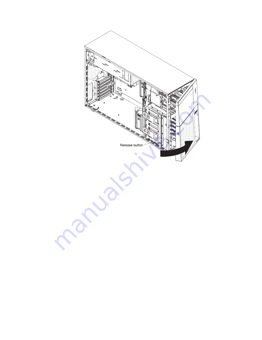
5. Remove the EMC shields from the drive bays.

6. Find the blue drive rails in the server bay and install one on each side of the

tape drive.

7. Slide the tape drive into the server.

8. Close the bezel.

9. Remove the power supplies from the rear of the server.

10. Carefully lay the server down on its side.

11. Open the power-supply cage (see “Opening the power-supply cage” on page

64 for more information).

12. Remove the air baffle (see “Removing the air baffle” on page 60 for more

information).

13. Remove the fan cage assembly.

Chapter 2. Installing optional devices

81

Summary of Contents for 7380E1U

Page 1: ...IBM System x3500 M3 Type 7380 Installation and User s Guide ...

Page 2: ......

Page 3: ...IBM System x3500 M3 Type 7380 Installation and User s Guide ...

Page 4: ...M Safety Information Environmental Notices and User Guide documents on the IBM Documentation CD and the Warranty Information document that comes with the server Sixth Edition April 2011 Copyright IBM Corporation 2011 US Government Users Restricted Rights Use duplication or disclosure restricted by GSA ADP Schedule Contract with IBM Corp ...

Page 5: ...oard external connectors 26 SAS backplane connectors 27 Operator information panel 28 Light path diagnostics panel 29 Installation guidelines 35 System reliability guidelines 36 Working inside the server with the power on 36 Handling static sensitive devices 37 Internal cable routing and connectors 38 Tape drive cable connection 38 DVD drive cable connection 41 Operator information panel cable con...

Page 6: ... access 121 Logging on to the Web interface 121 Enabling the Broadcom Gigabit Ethernet Utility program 122 Configuring the Gigabit Ethernet controller 122 Using the LSI Configuration Utility program 122 Starting the LSI Configuration Utility program 123 Formatting a hard disk drive 124 Creating a RAID array of hard disk drives 124 IBM Advanced Settings Utility program 124 Updating IBM Systems Dire...

Page 7: ... Industries Association JEITA statement 134 Korean Class A warning statement 134 Russia Electromagnetic Interference EMI Class A statement 135 People s Republic of China Class A electronic emission statement 135 Taiwan Class A compliance statement 135 Index 137 Contents v ...

Page 8: ...vi IBM System x3500 M3 Type 7380 Installation and User s Guide ...

Page 9: ...alleert eerst de veiligheidsvoorschriften Ennen kuin asennat tämän tuotteen lue turvaohjeet kohdasta Safety Information Avant d installer ce produit lisez les consignes de sécurité Vor der Installation dieses Produkts die Sicherheitshinweise lesen Prima di installare questo prodotto leggere le Informazioni sulla Sicurezza Les sikkerhetsinformasjonen Safety Information før du installerer dette prod...

Page 10: ... versions of the caution or danger statement in the IBM Safety Information document For example if a caution statement is labeled Statement 1 translations for that caution statement are in the Safety Information document under Statement 1 Be sure to read all caution and danger statements in this document before you perform the procedures Read any additional safety information that comes with the s...

Page 11: ...equipment when there is evidence of fire water or structural damage v Disconnect the attached power cords telecommunications systems networks and modems before you open the device covers unless instructed otherwise in the installation and configuration procedures v Connect and disconnect cables as described in the following table when installing moving or opening covers on this product or attached...

Page 12: ...ium battery replace it only with the same module type made by the same manufacturer The battery contains lithium and can explode if not properly used handled or disposed of Do not v Throw or immerse into water v Heat to more than 100 C 212 F v Repair or disassemble Dispose of the battery as required by local ordinances or regulations x IBM System x3500 M3 Type 7380 Installation and User s Guide ...

Page 13: ...the device v Use of controls or adjustments or performance of procedures other than those specified herein might result in hazardous radiation exposure DANGER Some laser products contain an embedded Class 3A or Class 3B laser diode Note the following Laser radiation when open Do not stare into the beam do not view directly with optical instruments and avoid direct exposure to the beam Class 1 Lase...

Page 14: ...e device and the power switch on the power supply do not turn off the electrical current supplied to the device The device also might have more than one power cord To remove all electrical current from the device ensure that all power cords are disconnected from the power source 1 2 xii IBM System x3500 M3 Type 7380 Installation and User s Guide ...

Page 15: ... inside any component that has this label attached There are no serviceable parts inside these components If you suspect a problem with one of these parts contact a service technician Statement 11 CAUTION The following label indicates sharp edges corners or joints nearby Statement 12 CAUTION The following label indicates a hot surface nearby Statement 13 Safety xiii ...

Page 16: ...al specifications Statement 15 CAUTION Make sure that the rack is secured properly to avoid tipping when the server unit is extended Statement 17 CAUTION The following label indicates moving parts nearby Statement 26 CAUTION Do not place any object on top of rack mounted devices Attention This product is suitable for use on an IT power distribution system whose maximum phase to phase voltage is 24...

Page 17: ...lity on page 11 You can obtain up to date information about the server and other IBM server products at http www ibm com systems x At http www ibm com support mysupport you can create a personalized support page by identifying IBM products that are of interest to you From this personalized page you can subscribe to weekly e mail notifications about new technical documents search for information an...

Page 18: ...___________________________________________ Key manufacturer _____________________________________________ Key phone number _____________________________________________ The model number and serial number are on labels on the bottom of the server and on the front visible through the bezel as shown in the following illustration Important The server keys cannot be duplicated by a locksmith If you lo...

Page 19: ... the following procedures If you are using a Windows operating system insert the CD into the CD or DVD drive and click Start Run In the Open field type e win32 bat where e is the drive letter of the CD or DVD drive and click OK If you are using Red Hat Linux insert the CD into the CD or DVD drive then run the following command from the mnt cdrom directory sh runlinux sh Select your server from the...

Page 20: ...ns of the IBM License Agreement for Machine Code for your product v IBM MCP Linux License Information and Attributions This document is in PDF on the IBM Documentation CD It provides the open source notices Depending on the server model additional documentation might be included on the IBM System x Documentation CD The System x and xSeries Tools Center is an online information center that contains...

Page 21: ... you avoid inconvenient or problem situations v Attention These notices indicate potential damage to programs devices or data An attention notice is placed just before the instruction or situation in which damage might occur v Caution These statements indicate situations that can be potentially hazardous to you A caution statement is placed just before the description of a potentially hazardous pr...

Page 22: ...nch hard disk drives the maximum number of RAID supported drives is 16 All the other drives will remain JBOD the drives are presented to the operating system without a RAID configuration If the server is configured for RAID operation using a ServeRAID adapter you might have to reconfigure your disk arrays after you install drives See the ServeRAID adapter documentation for additional information a...

Page 23: ...level 0 1 5 10 50 Note If the server is configured for RAID operation using a ServeRAID adapter you might have to reconfigure your disk arrays after you install drives See the ServeRAID adapter documentation for additional information about RAID operation and complete instructions for using the ServeRAID adapter Acoustical noise emissions v Sound power idle 5 5 bel declared v Sound power operating...

Page 24: ...ustry standard interfaces Intelligent Platform Management Interface IPMI version 2 0 Simple Network Management Protocol SNMP version 3 Common Information Model CIM Web browser v Remote presence capability and blue screen capture The remote presence feature provides the following functions Remotely viewing video with graphics resolutions up to 1600 x 1200 at 85 Hz regardless of the system state Rem...

Page 25: ...Setup and Installation CD see Using the ServerGuide Setup and Installation CD on page 116 v IBM X Architecture technology IBM X Architecture technology combines proven innovative IBM designs to make your Intel processor based server powerful scalable and reliable For more information see http www ibm com servers eserver xseries xarchitecture enterprise index html VMware ESXi embedded hypervisor Th...

Page 26: ...ding on your model 2 5 inch or eight 3 5 inch hard disk drives in the hot swap bays With the hot swap feature you can add remove or replace hard disk drives without turning off the server Note SAS expander card does not support 3 GB RAID adapters When using ServeRAID adapter M1015 to support more than sixteen 2 5 inch hard disk drives the maximum number of RAID supported drives is 16 All the other...

Page 27: ...tains an integrated management module IMM which enables you to manage the functions of the server locally and remotely and provides remote presence and blue screen capture capability The IMM also provides system monitoring and event recording v TCP IP offload engine TOE support The Ethernet controllers in the server support TOE which is a technology that offloads the TCP IP flow from the microproc...

Page 28: ...hernet adapter with failover support v Standby voltage for system management features and monitoring v System auto configuring from the configuration menu v System error LED on the front bezel and diagnostics LEDs on the system board v Upgradeable microcode for POST BIOS and read only memory ROM resident code locally or over a LAN v Vital product data VPD includes serial number information and rep...

Page 29: ...atures and functions to the base capabilities v Managing the life cycles of virtual resources For more information about IBM Systems Director see the documentation on the IBM Systems Director DVD that comes with the server and the IBM xSeries Systems Management Web page at http www ibm com systems management which presents an overview of IBM Systems Management and IBM Systems Director The UpdateXp...

Page 30: ...er the server is connected to ac power the power control button becomes active Off When this LED is off it indicates that AC power is not present or the power supply or the LED itself has failed A system power LED is also on the rear of the server Power control button Press this button to turn the server on and off manually A power control button shield comes with the server You can install this d...

Page 31: ...is flashing it indicates that the drive is in use Hard disk drive status LED On some server models each hot swap hard disk drive has a status LED When this LED is lit it indicates that the drive has failed If an optional IBM ServeRAID adapter is installed in the server when this LED is flashing slowly one flash per second it indicates that the drive is being rebuilt When the LED is flashing rapidl...

Page 32: ...agnostics panel is inside the front bezel Note The light path diagnostics LEDs remain lit only while the server is connected to power For more information about the light path diagnostics LEDs see the Problem Determination and Service Guide on the IBM Documentation CD 16 IBM System x3500 M3 Type 7380 Installation and User s Guide ...

Page 33: ...power supply has a DC power LED and an AC power LED When the DC power LED is lit it indicates that the power supply is supplying adequate DC power to the system During typical operation both the AC and DC power LEDs are lit For any other combination of LEDs see Power supply LEDs on page 18 Power error LED When the power error LED is lit it indicates that the power supply has failed Power cord conn...

Page 34: ...M The IMM can take control of the shared serial port to perform text console redirection and to redirect serial traffic using Serial over LAN SOL Video connector Connect a monitor to this connector Power supply LEDs The following illustration shows the power supply LEDs on the rear of the server For more information about solving power supply problems see the Problem Determination and Service Guid...

Page 35: ...s off replace the power supply 3 Trained service technician only If the system board error LED is lit replace the system board Typically indicates that a power supply is not fully seated On Off or Flashing On Faulty power supply Replace the power supply On On Off Normal operation On On On Power supply is faulty but still operational Replace the power supply Server power features When the server is...

Page 36: ...turn off the server See your operating system documentation for information about shutting down the operating system Statement 5 CAUTION The power control button on the device and the power switch on the power supply do not turn off the electrical current supplied to the device The device also might have more than one power cord To remove all electrical current from the device ensure that all powe...

Page 37: ...e Guide for information about how to run diagnostics 3 Follow the installation procedures in this chapter and use the correct tools Incorrectly installed devices can cause system failures because of damaged pins in sockets or connectors loose cabling or loose components 4 Use the best practices to apply current firmware and device driver updates for the server and optional devices To download the ...

Page 38: ...the server open or close a latch and so on Orange on a component or an orange label on or near a component indicates that the component can be hot swapped which means that if the server and operating system support hot swap capability you can remove or install the component while the server is running Orange can also indicate touch points on hot swap components See the instructions for removing or...

Page 39: ...one additional expansion slot The following illustration shows the additional PCI Express expansion slot that is available on the PCI Express extender card Note The PCI Express extender card comes standard in the System x3500 M3 server The following illustration shows two additional PCI X expansion slots that are available on the PCI X extender card Chapter 2 Installing optional devices 23 ...

Page 40: ...not asserted by default The physical presence needs to be asserted to activate deactivate clear or change ownership of the TPM Note If no jumper is present the server responds as on default position Table 4 System board switch 6 SW 6 Switches Switch description 1 Reserved default off 2 Power on password override when on default off 3 Reserved default off 4 When this switch is off the primary IMM f...

Page 41: ...System board LEDs The following illustration shows the LEDs on the system board Chapter 2 Installing optional devices 25 ...

Page 42: ...ystem board external connectors The following illustration shows the external input output connectors and the NMI button on the system board 26 IBM System x3500 M3 Type 7380 Installation and User s Guide ...

Page 43: ...ckplane connectors The following illustrations show the connectors on the SAS backplanes Figure 1 3 5 inch backplane connectors Figure 2 2 5 inch backplane connectors Chapter 2 Installing optional devices 27 ...

Page 44: ...nformation LED also lit Description System power green The states of the power on LED are as follows v Off AC power is not present or the power supply or the LED itself has failed v Flashing rapidly 4 times per second The server is turned off and is not ready to be turned on The power control button is disabled This will last approximately 20 to 40 seconds Note Approximately 20 seconds after the s...

Page 45: ...se IBM Systems Director to light this LED remotely System information amber When this amber LED is lit it indicates that information about a suboptimal condition in the server is available in the IMM event log or in the system event log Check the light path diagnostics panel for more information System error amber When this LED is lit it indicates that a system error has occurred Use the light pat...

Page 46: ...mperature see Environment in Features and specifications on page 6 System board BRD An error occurred on the system board 1 Check the LEDs on the system board to identify the component that is causing the error The BRD LED can be lit for the following conditions v Battery failure v Voltage regulator failure 2 Check the system event log for information about the error 3 Replace any failed or missin...

Page 47: ...starting the server each time a Power supply b Trained service technician only Power supply cage Hard disk drive RAID A hard disk drive SAS adapter or RAID adapter error has occurred Notes 1 This LED is lit also when a hard disk drive is removed from the server 2 The error LED on the failing hard disk drive is also lit 3 Check the system event log for a RAID error 1 Reinstall the removed drive 2 R...

Page 48: ...e CNFG LED is also lit which indicates the memory configuration is invalid If the CNFG LED is also lit then repopulate the DIMMs to a supported configuration 2 If the CNFG LED is not lit one of the following conditions is present v The server did not start and a failing DIMM LED is lit a Check for a PFA log event in the System Event Log SEL b Reseat the DIMM c Move the DIMM to a different slot or ...

Page 49: ...stem error LED MEM LED and CNFG LED are lit when POST detects an invalid memory configuration Remove and install supported DIMMs see Installing a memory module on page 86 3 The VRM LED and the CNFG LED are lit when POST detects a missing VRM for the second microprocessor Install a VRM in the VRM connector on the system board for the second microprocessor 4 Check the system event log for informatio...

Page 50: ... failing system board 3 If the CNFG LED is lit and the CPU mismatch LED on the system board is lit an invalid microprocessor configuration has occurred a Make sure that the microprocessors are compatible with each other They must match in speed and cache size To compare the microprocessor information run the Setup utility and select System Information and then select System Summary Select Processo...

Page 51: ...er is not working correctly see the Problem Determination and Service Guide on the IBM Documentation CD for information about how to run diagnostics v Observe good housekeeping in the area where you are working Place removed covers and other parts in a safe place v If you must start the server while the cover is removed make sure that no one is near the server and that no tools or other objects ha...

Page 52: ...periods of time more than 30 minutes with the left side cover removed might damage server components v You have followed the cabling instructions that come with optional adapters v You have replaced a failed fan within 48 hours v You have replaced a hot swap drive within 2 minutes of removal v You have replaced a hot swap fan within 30 seconds of removal v You do not remove the air duct or air baf...

Page 53: ...e wrist strap if one is available v Handle the device carefully holding it by its edges or its frame v Do not touch solder joints pins or exposed circuitry v Do not leave the device where others can handle and damage it v While the device is still in its static protective package touch it to an unpainted metal part of the server for at least 2 seconds This drains static electricity from the packag...

Page 54: ... attached If you replace any drives remember which cable is attached to which drive v When you route a cable make sure that it does not block the airflow to the rear of the drives or over the microprocessor or DIMMs Tape drive cable connection You can install either a USB or SATA tape drive in the server The following illustration shows the internal cable routing and connectors for both the USB ta...

Page 55: ...traditional power converter cable when you install an RDX internal USB tape drive in the server This cable comes with the server in the plastic bag with the drive rails Connects to tape drive Connects to optical power cable Power converter cable Chapter 2 Installing optional devices 39 ...

Page 56: ...Power converter cable Optical power cable SATA connector Tape drive 40 IBM System x3500 M3 Type 7380 Installation and User s Guide ...

Page 57: ...ternal SATA and power cable routing and the connectors from the DVD drive to the system board The following illustration shows the internal power cable routing and the connectors from the UltraSlim DVD drive to the system board Chapter 2 Installing optional devices 41 ...

Page 58: ...The following illustration shows the internal SATA cable routing and the connectors from the UltraSlim DVD drive to the system board 42 IBM System x3500 M3 Type 7380 Installation and User s Guide ...

Page 59: ...ing and connectors from the operator information panel to the system board Light path diagnostics LED panel cable connection The following illustration shows the internal cable routing and connectors from the light path diagnostics LED panel to the system board Chapter 2 Installing optional devices 43 ...

Page 60: ...o internal drives 1 The following illustrations show the connectors on the 2 5 inch and 3 5 inch hard disk drive backplanes Figure 3 Connectors on the 3 5 inch hard disk drive backplane Figure 4 Connectors on the 2 5 inch hard disk drive backplane 44 IBM System x3500 M3 Type 7380 Installation and User s Guide ...

Page 61: ...strations show the cable connectors on ServeRAID M1015 M5014 M5015 adapters Figure 5 Cable connectors on ServeRAID M1015 adapter Figure 6 Cable connectors on ServeRAID M5014 adapter Chapter 2 Installing optional devices 45 ...

Page 62: ...l any card in slot 3 v If the server is configured for RAID operation using a ServeRAID adapter you might have to reconfigure your disk arrays after you install drives See the ServeRAID adapter documentation for additional information about RAID operation and complete instructions for using the ServeRAID adapter Figure 7 Cable connectors on ServeRAID M5015 adapter 46 IBM System x3500 M3 Type 7380 ...

Page 63: ... four 3 5 inch hot swap hard disk drives v The following illustration shows the internal power cable routing v The following illustration shows the internal configuration cable routing v The following illustration shows the internal signal cable routing for installing a ServeRAID adapter Chapter 2 Installing optional devices 47 ...

Page 64: ...48 IBM System x3500 M3 Type 7380 Installation and User s Guide ...

Page 65: ...owing illustration shows the internal power cable routing v The following illustration shows the internal configuration cable routing v The following illustration shows the internal signal cable routing for installing a ServeRAID adapter Chapter 2 Installing optional devices 49 ...

Page 66: ...50 IBM System x3500 M3 Type 7380 Installation and User s Guide ...

Page 67: ...owing illustration shows the internal power cable routing v The following illustration shows the internal configuration cable routing v The following illustration shows the internal signal cable routing for installing a ServeRAID adapter Chapter 2 Installing optional devices 51 ...

Page 68: ...52 IBM System x3500 M3 Type 7380 Installation and User s Guide ...

Page 69: ...sixteen 2 5 inch hot swap hard disk drives v The following illustration shows the internal power cable routing v The following illustration shows the internal configuration cable routing Chapter 2 Installing optional devices 53 ...

Page 70: ...shows the internal signal cable routing for installing a ServeRAID adapter and a ServeRAID expansion adapter Note SAS expander card does not support 3 GB RAID adapters 54 IBM System x3500 M3 Type 7380 Installation and User s Guide ...

Page 71: ...enty four 2 5 inch hot swap hard disk drives v The following illustration shows the internal power cable routing v The following illustration shows the internal configuration cable routing Chapter 2 Installing optional devices 55 ...

Page 72: ... card does not support 3 GB RAID adapters When using ServeRAID adapter M1015 to support more than sixteen 2 5 inch hard disk drives the maximum number of RAID supported drives is 16 All the other drives will remain JBOD the drives are presented to the operating system without a RAID configuration 56 IBM System x3500 M3 Type 7380 Installation and User s Guide ...

Page 73: ... that begins on page vii and Installation guidelines on page 35 2 If you are planning to view the error LEDs that are on the system board and components leave the server connected to power and go directly to step 5 3 Turn off the server and all attached devices 4 Disconnect all external cables and power cords 5 Using the supplied key unlock the left side cover 6 Pull the cover release latch down a...

Page 74: ...open or remove the bezel When you lock the left side cover it locks both the cover and the bezel 3 Press the button on the left edge of the bezel and rotate the left side of the bezel away from the server 4 From inside of the top section of the bezel door slide the blue tab up to unlock the bezel media door then grasp the depressed area on the left side of the media door and pull the door open 58 ...

Page 75: ...om the bezel push upward on the media door hinge to remove it from the bezel 5 When the media door is unlocked the icon on the side of the bezel will be in the unlocked position Media door icon Chapter 2 Installing optional devices 59 ...

Page 76: ...er cords 4 Remove the left side cover see Removing the left side cover on page 57 for more information 5 Remove the power supplies from the power supply cage 6 Unlatch the power supply cage and rotate it out of the server until it locks 7 Rotate the rear of the air baffle up 1 Find the pinch tab on the air baffle pinch it together with your fingers 2 and lift the air baffle out of the server 3 60 ...

Page 77: ...licks into place 3 Rotate the rear hinged part of the air baffle 2 down to the system board Note Make sure that the power supply cage cables are not caught under the air baffle 4 Return the power supply cage to its closed position see Closing the power supply cage on page 65 5 Install the hot swap power supply or power supplies see Installing a redundant power supply and fans on page 102 6 Install...

Page 78: ...mbly with the guide rails on the sides of the chassis Note Make sure that both release buttons click into place 2 Slide the fan cage assembly into the chassis and press firmly until the fan cage is seated firmly in place 3 Install the air baffle see Installing the air baffle on page 61 4 Rotate the power supply cage assembly back into the server Press the power supply release tab and rotate the po...

Page 79: ...Chapter 2 Installing optional devices 63 ...

Page 80: ...es 3 Press the release latch on the power supplies and pull them out of the power supply cage Hot swap power supply Release latch 4 Unlock and remove the left side cover see Removing the left side cover on page 57 for more information 5 Pull up on the power supply cage handle to unlock the cage then rotate the cage out until it stops The tab on the rear power supply latch bracket clicks into place...

Page 81: ...wer supply support bracket Power supply support bracket Power supply release tab Attention Be sure to move the cables out of the way of the power supply cage before you start to move the cage back into the server 2 Carefully rotate the power supply cage into the server chassis The locating tabs on the power supply cage must fit over the corresponding tabs on the front latch bracket Chapter 2 Insta...

Page 82: ...notch in the front latch bracket then lower the handle until it locks in place Power supply cage closed 4 Install and lock the left side cover see Completing the installation on page 105 5 Install the hot swap power supplies 6 Reconnect the external cables and power cords then turn on the attached devices and turn on the server 66 IBM System x3500 M3 Type 7380 Installation and User s Guide ...

Page 83: ...ion Revision 2 0 compliant Slot 6 is a PCI 33 32 slot PCI 2 2 compliant PCI Express extender card slot 7 is a PCI Express x8 slot with x4 links PCI Express 1 0a compliant Note The PCI Express extender card comes standard on the System x3500 M3 server PCI X extender card slots 7 and 8 are PCI X slots with 64 32 bits 133 100 66 MHz from PXH v The system scans PCI slots 1 through 6 to assign system r...

Page 84: ...ation that comes with the adapter for any cabling instructions and information about jumper or switch settings It might be easier for you to route cables before you install the adapter 4 Rotate the adapter retention brackets to the open position 5 Remove the expansion slot cover 6 If you are installing a full length adapter remove the blue adapter guide if any from the end of the adapter Otherwise...

Page 85: ...acket is in the closed position Attention Incomplete insertion might cause damage to the system board or the adapter 8 Connect any needed cables to the adapter If you have other devices to install or remove do so now Otherwise go to Completing the installation on page 105 Chapter 2 Installing optional devices 69 ...

Page 86: ... guidelines on page 35 b Turn off the server and peripheral devices and disconnect the power cords and all external cables c Unlock and remove the left side cover see Removing the left side cover on page 57 d Remove the fan cage assembly e Open the bezel by pressing the button on the left edge of the bezel and rotate the left side of the bezel away from the server 70 IBM System x3500 M3 Type 7380 ...

Page 87: ...ve the EMC shield from the bay in which you want to install the drive Note If you are installing a drive that contains a laser observe the following safety precaution Chapter 2 Installing optional devices 71 ...

Page 88: ...nts and avoid direct exposure to the beam Class 1 Laser Product Laser Klasse 1 Laser Klass 1 Luokan 1 Laserlaite Appareil A Laser de Classe 1 g Touch the static protective package that contains the DVD drive to any unpainted metal surface on the server then remove the DVD drive from the package and place it on a static protective surface h Set any jumpers or switches on the drive according to the ...

Page 89: ...ors on page 23 and Internal cable routing and connectors on page 38 for more information l Route the signal cable through the plastic slot on the bottom of the chassis underneath the fan cage assembly so that it does not block the airflow m Reinstall the fan cage assembly n Reinstall the air baffle see Installing the air baffle on page 61 o Rotate the power supply cage assembly back into the serve...

Page 90: ...ntation that comes with the new drive v You have checked the instructions that come with the new drive to determine whether you must set any switches or jumpers in the drive v You have removed the blue optical drive rails from the side of the old drive and have them available for installation on the new drive Note If you are installing a drive that contains a laser observe the following safety pre...

Page 91: ...ltraSlim DVD drive to any unpainted metal surface on the server then remove the UltraSlim DVD drive from the package c Read the safety information that begins on page vii and Installation guidelines on page 35 d Turn off the server and peripheral devices and disconnect the power cords and all external cables e Unlock and remove the left side cover see Removing the left side cover on page 57 f Remo...

Page 92: ...e way up until the retainer latch locks the cage in place on the chassis i Disconnect the power and signal cables of the DVD drive from the system board j Pull the power and signal cables of the UltraSlim DVD drive through the slim slot on top of the 3 5 inch hard disk drive cage 76 IBM System x3500 M3 Type 7380 Installation and User s Guide ...

Page 93: ...ll the power and signal cables of the UltraSlim DVD drive into the slim slot on top of the cage first Make sure the cables are not stuck when you slide the UltraSlim DVD drive into the cage n Slide the 3 5 inch disk drive cage into the upper opening of the server along the lower edge of the opening Note Pull the power and signal cables of the UltraSlim DVD drive into the upper opening of the serve...

Page 94: ...ore information q Reinstall the air baffle r Reinstall the fan cage assembly s Rotate the power supply cage assembly back into the server Press the power supply cage release tab and rotate the power supply cage assembly into the chassis t Close the bezel u Install and lock the left side cover see Completing the installation on page 105 78 IBM System x3500 M3 Type 7380 Installation and User s Guide...

Page 95: ...les and power cords then turn on the attached devices and turn on the server If you have other devices to install or remove do so now Otherwise go to Completing the installation on page 105 Chapter 2 Installing optional devices 79 ...

Page 96: ...information that begins on page vii and Installation guidelines on page 35 2 Turn off the server and peripheral devices and disconnect the power cords and all external cables 3 Unlock and remove the left side cover see Removing the left side cover on page 57 for more information 4 Open the bezel by pressing the button on the left edge of the bezel and rotate the left side of the bezel away from th...

Page 97: ...er 8 Close the bezel 9 Remove the power supplies from the rear of the server 10 Carefully lay the server down on its side 11 Open the power supply cage see Opening the power supply cage on page 64 for more information 12 Remove the air baffle see Removing the air baffle on page 60 for more information 13 Remove the fan cage assembly Chapter 2 Installing optional devices 81 ...

Page 98: ...ble to the back of the tape drive see Internal cable routing and connectors on page 38 for more information Note If you are installing an RDX internal USB tape drive use the SATA to traditional power converter cable to serve as a bridge between the optical power cable and the power connector on the RDX tape drive 16 Connect the power cable to the tape drive and to the connector on the system board...

Page 99: ...ly cage on page 65 for more information 20 Reinstall the power supplies 21 Replace the left side cover then lock the side cover and bezel 22 Reconnect the external cables and power cords If you have other devices to install or remove do so now Otherwise go to Completing the installation on page 105 Chapter 2 Installing optional devices 83 ...

Page 100: ...ls with four 3 5 inch hard disk drives the drive numbers are 0 through 3 left to right On models with eight 3 5 inch hard disk drives hard disk drive cage for drive 4 through 7 left to right is added v For a list of supported optional devices for the server see http www ibm com servers eserver serverproven compat us v Inspect the drive tray for signs of damage v Make sure that the drive is correct...

Page 101: ... correctly If the amber hard disk drive status LED is lit continuously that drive is faulty and must be replaced If the green hard disk drive activity LED is flashing the drive is being accessed 2 If the server is configured for RAID operation through an optional ServeRAID adapter you might have to reconfigure your disk arrays after you install hard disk drives See the ServeRAID documentation on t...

Page 102: ... per microprocessor improves server performance v When two microprocessors are installed in the server distribute the DIMMs between the two microprocessors to improve server performance v The server supports a maximum of 16 single dual or quad rank DIMMs The maximum number of quad rank DIMMs the server supports is 12 v The maximum number of single dual rank ECC supported UDIMM the server supports ...

Page 103: ...Max performance mode v Two 1 35 V single rank or dual ranl RDIMMs are installed in the same channel In the Setup utility Memory speed is set to Max performance and LV DIMM power is set to Enhance performance mode The 1 35 V RDIMMs will function at 1 5 V The following notes describe the types of DIMMs that the server supports and other information that you must consider when you install DIMMs v Whe...

Page 104: ...equency Do not install registered and unbuffered DIMMs in the same server v The maximum memory speed is determined by the combination of the microprocessor DIMM speed and the number of DIMMs installed in each channel v In two DIMM per channel configuration a server with an Intel Xeon X5600 series microprocessor automatically operates with a maximum memory speed of up to 1333 MHz when one of the fo...

Page 105: ...he Setup utility For additional information see Chapter 3 Configuring the server on page 107 v When you install one quad rank RDIMM in a channel install it in the DIMM connector furthest away from the microprocessor v Do not install one quad rank RDIMM in one channel and three RDIMMs in another channel Independent channel mode The server requires at least one installed DIMM The server comes with a...

Page 106: ...irroring mode v The maximum amount of available memory is reduced to half of the amount of installed memory when memory mirroring is enabled For example if you install 64 GB of memory only 32 GB of addressable memory is available when you use memory mirroring The following illustration shows the memory channel interface layout with the DIMM installation sequence for memory mirroring mode The numbe...

Page 107: ...roprocessor 2 as soon as you install microprocessor 2 you do not have to wait until all of the DIMM connectors for microprocessor 1 are filled The following table lists the installation sequence for installing DIMMs in memory mirroring mode Table 8 Memory mirroring mode DIMM population sequence DIMMs Number of installed microprocessors DIMM connector First pair of DIMMs 1 3 6 Second pair of DIMMs ...

Page 108: ... and all external cables 3 Remove the left side cover see Removing the left side cover on page 57 4 Remove the hot swap power supply or power supplies from the server 5 Pull up the power supply cage handle and then swing the power supply cage out of the server see Opening the power supply cage on page 64 for more information 6 Remove the air baffle from the server see Removing the air baffle on pa...

Page 109: ...sparing This feature disables the failed memory from the system configuration and activates a DIMM to replace the failed active DIMM You can enable either memory sparing or memory mirroring in the Setup utility see Using the Setup utility on page 108 When you use the memory sparing feature consider the following information v The memory sparing feature is supported on server models with an Intel X...

Page 110: ...an optional ServeRAID adapter advanced feature key To install an optional ServeRAID adapter advanced feature key complete the following steps 1 Read the safety information that begins on page vii and Installation guidelines on page 35 2 Turn off the server and peripheral devices and disconnect the power cords 3 Remove the left side cover see Removing the left side cover on page 57 4 Rotate the ada...

Page 111: ...bedded hypervisor flash device To install a hypervisor flash device complete the following steps 1 Read the safety information that begins on page vii and Installation guidelines on page 35 2 Turn off the server and peripheral devices and disconnect the power cords 3 Remove the left side cover see Removing the left side cover on page 57 4 Unlock the retention latch by pushing it down toward the sy...

Page 112: ...n the retention latch to the locked position by pulling it away from the system board 7 Reconnect the power cord and any cables that you removed 8 Install and lock the left side cover see Completing the installation on page 105 9 Turn on the peripheral devices and the server 96 IBM System x3500 M3 Type 7380 Installation and User s Guide ...

Page 113: ...ibm com systems support 2 Under Product support click System x 3 Under Popular links click Software and device drivers 4 Click System x3500 M3 to display the matrix of downloadable files for the server v Optional Obtain an SMP capable operating system For a list of supported operating systems and optional devices see http www ibm com servers eserver serverproven compat us v To order additional mic...

Page 114: ...wer cords and all external cables Remove the left side cover see Removing the left side cover on page 57 for more information 3 Remove the hot swap power supplies from the server 4 Open the power supply cage see Opening the power supply cage on page 64 for more information 5 Remove the air baffle see Removing the air baffle on page 60 for more information 6 Locate the second microprocessor socket ...

Page 115: ...you try to close the lever 9 Install the microprocessor a Touch the static protective package that contains the microprocessor to any unpainted metal surface on the server Then remove the microprocessor from the package b Remove the protective cover tape or label from the surface of the microprocessor socket if any is present c Align the microprocessor with the socket The microprocessor has two no...

Page 116: ...rmal grease will contaminate it If the thermal grease is contaminated call IBM service and support to request a replacement thermal grease kit For information about installing the replacement thermal grease see the Problem Determination and Service Guide a Make sure that the heat sink release lever is in the fully open position b Remove the plastic protective cover from the bottom of the heat sink...

Page 117: ...ith the connector c Insert the VRM into the connector by aligning the edges of the VRM with the slots at the end of the VRM connector Firmly press the VRM straight down into the connector by applying pressure on both ends of the VRM simultaneously The retaining clips snap into the locked position when the VRM is seated in the connector 14 Reinstall the air baffle see Installing the air baffle on p...

Page 118: ...ote Do not allow the server to fall over 4 Remove the three fan air baffles from the fan bays of the fan cage assembly with your finger Slide the orange release tab in the direction indicated by the arrow on top of the fan to unlock the fan handle Grasp the fan handle and pull the fan out of the fan cage assembly Hot swap fan 5 If you are instructed to return the hot swap fan follow all packaging ...

Page 119: ...rking inside the server with the power on 9 Remove the power supply filler from the second power supply bay 10 Slide the new power supply partially into the empty power supply bay Pinch the orange release latch and push the power supply the rest of the way into the bay until it is seated 11 Install the left side cover see Completing the installation on page 105 12 Connect one end of the new power ...

Page 120: ...ply is operating correctly If the server is turned on make sure that the DC power LED on the top of the power supply is lit also If you have other devices to install or remove do so now Otherwise go to Completing the installation on page 105 104 IBM System x3500 M3 Type 7380 Installation and User s Guide ...

Page 121: ...ft side cover and bezel 7 Connect the cables and power cords For more information see Connecting the cables Connecting the cables Notes 1 Be sure to turn off the server before you connect any cables to or disconnect any cables from the server or hot plug adapter 2 For additional cabling instructions see the documentation that comes with the optional devices It might be easier for you to route any ...

Page 122: ...evices have device drivers that you must install For information about installing device drivers see the documentation that comes with each device The server comes with at least one microprocessor If more than one microprocessor is installed the server can operate as a symmetric multiprocessing SMP server You might have to upgrade the operating system to support SMP For more information see Typica...

Page 123: ...agement module IMM for configuration to update the firmware and sensor data record field replaceable unit SDR FRU data and to remotely manage a network For information about using the IMM see Using the integrated management module on page 118 and the IMM User s Guide on the IBM Web Site v Remote presence capability and blue screen capture The remote presence and blue screen capture feature are int...

Page 124: ...ge Manager MSM Director ServeRAID M5014 adapter LSI SAS2108 MegaRAID BIOS Configuration Utility ServerGuide MegaRAID Storage Manager MSM Director ServeRAID M5015 adapter LSI SAS2108 MegaRAID BIOS Configuration Utility ServerGuide MegaRAID Storage Manager MSM Director ServeRAID M1015 adapter LSI SAS2008 MegaRAID BIOS Configuration Utility ServerGuide MegaRAID Storage Manager MSM Director v IBM Adva...

Page 125: ...ctly in the system information This choice is on the full Setup utility menu only System Summary Select this choice to view configuration information including the ID speed and cache size of the microprocessors machine type and model of the server the serial number the system UUID and the amount of installed memory When you make configuration changes through other choices in the Setup utility the ...

Page 126: ...s choice to view or change power capping to control consumption processors and performance states Legacy Support Select this choice to view or set legacy support Force Legacy Video on Boot Select this choice to force INT video support if the operating system does not support UEFI video output standards Rehook INT 19h Select this choice to enable or disable devices from taking control of the boot p...

Page 127: ...ivers Select this choice to view information about the adapters and device drivers in the server that are compliant with EFI 1 10 and UEFI 2 0 v Network Select this choice to view or configure the network options such as the iSCSI PXE and network devices There might be additional configuration choices for optional network devices that are compliant with UEFI 2 1 and later v Date and Time Select th...

Page 128: ... to set or change a power on password For more information see Power on password on page 114 Clear Power on Password Select this choice to clear a power on password For more information see Power on password on page 114 Set Administrator Password Select this choice to set or change an administrator password An administrator password is intended to be used by a system administrator it limits access...

Page 129: ...e previous settings v Load Default Settings Select this choice to cancel the changes that you have made in the settings and restore the factory settings v Exit Setup Select this choice to exit from the Setup utility If you have not saved the changes that you have made in the settings you are asked whether you want to save the changes or exit without saving them Chapter 3 Configuring the server 113...

Page 130: ...imited Setup utility menu the user can set change and delete the power on password if the system administrator has given the user that authority Power on password If a power on password is set when you turn on the server the system startup will not be completed until you type the power on password You can use any combination of up to seven characters A Z a z and 0 9 for the password When a power o...

Page 131: ...ion The power on password override jumper does not affect the administrator password Attention If you set an administrator password and then forget it there is no way to change override or remove it You must replace the system board Administrator password An administrator password is intended to be used by a system administrator it limits access to the full Setup utility menu If an administrator p...

Page 132: ...urn off the server then move the UEFI boot recovery JP6 jumper back to the primary position pins 1 and 2 Using the ServerGuide Setup and Installation CD The ServerGuide Setup and Installation CD contains a setup and installation program that is designed for your server The ServerGuide program detects the server model and optional hardware devices that are installed and uses that information during...

Page 133: ... operating system installation Setup and configuration overview When you use the ServerGuide Setup and Installation CD you do not need setup diskettes You can use the CD to configure any supported IBM server model The setup program provides a list of tasks that are required to set up your server model On a server with a ServeRAID adapter or integrated SCSI controller with RAID capabilities you can...

Page 134: ...installation program for the operating system takes control to complete the installation Installing your operating system without using ServerGuide If you have already configured the server hardware and you are not using the ServerGuide program to install your operating system complete the following steps to download the latest operating system installation instructions from the IBM Web site Note ...

Page 135: ...s v NMI detection and reporting v Operating system failure blue screen capture v PCI configuration data v PECI 2 support v Power reset control power on hard and soft shutdown hard and soft reset schedule power control v Query power supply input power v ROM based IMM firmware flash updates v Serial over LAN SOL v Serial redirect v System event log v When one of the two microprocessors reports an in...

Page 136: ...pervisor flash device image becomes corrupt you can use the VMware Recovery CD that comes with the system to recover the flash device image To recover the flash device image complete the following steps 1 Turn on the server Note Approximately 20 seconds after the server is connected to AC power the power control button becomes active 2 Insert the VMware Recovery CD into the DVD drive 3 Follow the ...

Page 137: ...rite it down 7 Exit from the Setup utility Logging on to the Web interface To log on to the Web interface to use the remote presence functions complete the following steps 1 Open a Web browser on a computer that connects to the server and in the address or URL field type the IP address or host name of the IMM to which you want to connect Notes a If you are logging on to the IMM for the first time ...

Page 138: ...the data transfer rate 10BASE T 100BASE TX or 1000BASE T and duplex mode full duplex or half duplex of the network and automatically operate at that rate and mode You do not have to set any jumpers or configure the controllers However you must install a device driver to enable the operating system to address the controllers To find updated information about configuring the controllers complete the...

Page 139: ...e an integrated SAS SATA adapter with RAID capabilities to configure a RAID 1 mirrored array after you have installed the operating system you will lose access to any data or applications that were previously stored on the secondary drive of the mirrored pair v If you install a different type of ServeRAID adapter see the documentation that comes with the adapter for information about viewing and c...

Page 140: ...Properties 3 Select the type of array that you want to create 4 In the RAID Disk column use the Spacebar or Minus key to select Yes select or No deselect to select or deselect a drive from a RAID disk 5 Continue to select drives using the Spacebar or Minus key until you have selected all the drives for your array 6 Press C to create the disk array 7 Select Save changes then exit this menu to creat...

Page 141: ... the IBM Systems Director Web interface click View updates 3 Click Check for updates The available updates are displayed in a table 4 Select the updates that you want to install and click Install to start the installation wizard If your management server is not connected to the Internet to locate and install updates and interim fixes complete the following steps 1 Make sure that you have run the D...

Page 142: ...126 IBM System x3500 M3 Type 7380 Installation and User s Guide ...

Page 143: ...agnostic tests that you can perform Most systems operating systems and programs come with documentation that contains troubleshooting procedures and explanations of error messages and error codes If you suspect a software problem see the documentation for the operating system or program Using the documentation Information about your IBM system and preinstalled software if any or optional device is...

Page 144: ...In the U S and Canada call 1 800 IBM SERV 1 800 426 7378 Hardware service and support You can receive hardware service through your IBM reseller or IBM Services To locate a reseller authorized by IBM to provide warranty service go to http www ibm com partnerworld and click Find a Business Partner on the right side of the page For IBM support telephone numbers see http www ibm com planetwide In the...

Page 145: ...ss or implied warranties in certain transactions therefore this statement may not apply to you This information could include technical inaccuracies or typographical errors Changes are periodically made to the information herein these changes will be incorporated in new editions of the publication IBM may make improvements and or changes in the product s and or the program s described in this publ...

Page 146: ... is it intended to be used in a public services network Processor speed indicates the internal clock speed of the microprocessor other factors also affect application performance CD or DVD drive speed is the variable read rate Actual speeds vary and are often less than the possible maximum When referring to processor storage real and virtual storage or channel volume KB stands for 1024 bytes MB st...

Page 147: ...ation of appropriate remedial measures to mitigate such environmental contamination Implementation of such remedial measures is a customer responsibility Table 11 Limits for particulates and gases Contaminant Limits Particulate v The room air must be continuously filtered with 40 atmospheric dust spot efficiency MERV 9 according to ASHRAE Standard 52 21 v Air that enters a data center must be filt...

Page 148: ...t in a residential area is likely to cause harmful interference in which case the user will be required to correct the interference at his own expense Properly shielded and grounded cables and connectors must be used in order to meet FCC emission limits IBM is not responsible for any radio or television interference caused by using other than recommended cables and connectors or by unauthorized ch...

Page 149: ...t entspricht den Schutzanforderungen der EU Richtlinie 2004 108 EG zur Angleichung der Rechtsvorschriften über die elektromagnetische Verträglichkeit in den EU Mitgliedsstaaten und hält die Grenzwerte der EN 55022 Klasse A ein Um dieses sicherzustellen sind die Geräte wie in den Handbüchern beschrieben zu installieren und zu betreiben Des Weiteren dürfen auch nur von der IBM empfohlene Kabel anges...

Page 150: ...71137 Ehningen Germany Telephone 49 7032 15 2937 Email tjahn de ibm com Generelle Informationen Das Gerät erfüllt die Schutzanforderungen nach EN 55024 und EN 55022 Klasse A VCCI Class A statement This is a Class A product based on the standard of the Voluntary Control Council for Interference VCCI If this equipment is used in a domestic environment radio interference may occur in which case the u...

Page 151: ...Russia Electromagnetic Interference EMI Class A statement People s Republic of China Class A electronic emission statement Taiwan Class A compliance statement Appendix B Notices 135 ...

Page 152: ...136 IBM System x3500 M3 Type 7380 Installation and User s Guide ...

Page 153: ...uting 44 updating 106 updating server 107 configuration continued with ServerGuide 117 configuration programs LSI Configuration Utility 108 connecting the cables 105 connector Ethernet 17 connectors on front of server 13 rear of server 17 SAS backplane 27 system board 23 contamination particulate and gaseous 131 controller configuring Ethernet 122 controls 13 cooling 11 cover removing 57 CPU LED 3...

Page 154: ...nued connectors 27 formatting 124 installation 85 LED 31 status LED 15 types and installation information 84 hardware service and support 128 heat output 7 heat sink 100 help getting 127 humidity 7 I IBM Advanced Settings Utility program overview 124 IBM Support Line 128 IBM Systems Director overview 12 server feature 9 updating 125 IBM X Architecture technology 9 ID location hard disk drive 84 IM...

Page 155: ...e 93 menu choices in Setup utility 109 microprocessor 6 11 microprocessor continued heat sink 100 installation 98 type and installation information 97 mirroring mode 90 N network options 111 NMI LED 31 noise emissions 7 notes 5 notes important 130 notices 129 electronic emission 132 FCC Class A 132 notices and statements 5 O obtaining IP address for Web interface 121 online documentation 1 publica...

Page 156: ...21 serviceability 11 settings 113 setup and configuration with ServerGuide 117 Setup utility menu choices 109 starting 109 using 108 size 6 slots 6 SMP 11 software service and support 128 SP LED 34 specifications 6 Standby mode 19 start options 111 starting backup server firmware 116 LSI Configuration Utility 123 Setup utility 109 statements and notices 5 static sensitive devices handling 37 suppo...

Page 157: ...guration 106 107 USB connectors 18 USB or SATA tape drive 80 user security 112 using boot selection menu program 116 embedded hypervisor 120 LSI Configuration Utility 122 remote presence feature 120 ServerGuide 116 Setup utility 108 V video connector 18 VRM installation 101 LED 33 W Web interface logging on to 121 obtaining IP address 121 web site publication ordering 127 ServerGuide 116 support 1...

Page 158: ...142 IBM System x3500 M3 Type 7380 Installation and User s Guide ...

Page 159: ......

Page 160: ... Part Number 81Y6295 Printed in USA 1P P N 81Y6295 ...

Reviews: