background image

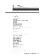
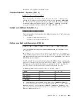
RM

Right Margin

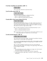
SOP

Skip Over Perforation

PL

Page Length

Notes:

1. The host should set the limits of the presentation surface if the default or

previous values are not acceptable.

2. The operator should align the physical paper so that it matches the logical

presentation surface.

Also created with this surface is a pair of numbers (CPL and CPP) which specify
the line number and column number where the next graphic will be printed. These
internal values are the logical position on the presentation surface.

The variable parameters have default values which are established when the printer
is initialized. The standard power-on defaults are:

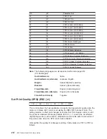
TOF

Operator panel setting

PL

Operator panel setting

CPI

Operator panel setting

LPI

Operator panel setting

LM

0 inches (Column 1)

RM

Operator panel setting

SOP

Operator panel setting

HT

Horizontal tabs are set at each 8th column, starting with column 9 (9, 17,
25, 33, and so on)

VT

Vertical tabs are all cleared

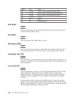
One-Byte Controls

Note: Control hex values within parentheses are recognized only within PC

Character Set 1.

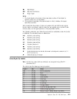
The printer uses the following one-byte controls:

Control

Hex

Name

NUL

00 (80)

Null (no operation)

BEL

07 (87)

Bell

BS

08 (88)

Backspace

HT

09 (89)

Horizontal Tab

LF

0A (8A)

Line Feed

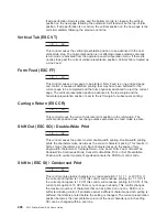
VT

0B (8B)

Vertical Tab

FF

0C (8C)

Form Feed

CR

0D (8D)

Carriage Return

SO

0E (8E)

Shift Out (Double-Wide Print)

SI

0F (8F)

Shift In (Condensed Print)

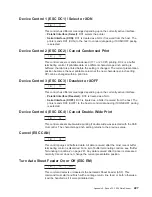
DC1

11 (91)

Device Control 1 (Parallel Select, Serial XON)

Appendix E. Epson FX-1050 Data Stream

219

Summary of Contents for 4247 A00

Page 1: ...4247 Printer Model A00 User s Guide SA24 4404 02 IBM ...

Page 2: ......

Page 3: ...4247 Printer Model A00 User s Guide SA24 4404 02 IBM ...

Page 4: ...rving your locality Publications are not stocked at the address below A Readers Comments form is provided at the back of this publication You may send your comments by facsimile to 1 800 524 1519 by electronic mail to print_pubs printers ibm com or by mail to IBM Printing Systems Company Department H7FE Building 003G Information Development PO Box 1900 Boulder CO 80301 9191 USA Internet Visit our ...

Page 5: ...ge 17 Connecting Electrical Power 18 Changing Display Language 19 Stacking Forms for Front Push Forms Path 20 Loading Forms into Front Push Forms Path 20 Creating Print Test Sample Self Test Printout with Firmware Level 23 Tearing Off Forms 24 Choosing Tear Off Option 25 Checking and Adjusting Tear Off Position 25 Checking Configuration 27 Printing Power On Configuration Setup 27 Printing Program ...

Page 6: ...and Loading Another Dual Push 59 Setting Up Rear Pull Forms Path 60 Installing Rear Pull Tractor 61 Configuring Forms Path for Rear Pull 63 Loading Forms For Rear Pull 64 Setting Up Push Pull Forms Path 70 Installing Push Pull Tractors 71 Configuring Forms Path for Push Pull 71 Loading Forms For Push Pull 72 Chapter 4 Configuring Your Printer 79 Operator Panel Function Keys Used for Configuration ...

Page 7: ...bon Cartridge 133 Removing Ribbon Cartridge 133 Installing Ribbon Cartridge 135 Cleaning Printer 137 Cleaning Inside of Printer 137 Cleaning Covers 137 Clearing Forms Jams and Restarting a Print Job 137 Chapter 7 Resolving Printer Problems 139 About This Chapter 139 Status Codes and Messages 139 Various Problems 142 Printed Output Problems 142 Other Problems 143 Print Quality and Ribbon Problems 1...

Page 8: ...dix C Native 4247 Commands 171 Native Commands 171 Bar Code Commands 173 SELECT Command Format 173 PRINT Command Format 175 Bar Code Examples 176 Valid Bar Code Data 177 Reinitialize Printer Command 178 Set Vertical Spacing Inches 178 Set Vertical Spacing Metric 178 Character Horizontal Spacing 179 Forms Path Control 179 Select Resident Font 180 Select Emulation 180 Select AFTA in Column 181 Selec...

Page 9: ... CAN 196 Turn Auto Sheet Feeder On or Off ESC EM 196 Auto Underscore ESC 196 Set 1 8 Inch Line Spacing ESC 0 196 Set 7 72 Inch Line Spacing ESC 1 197 Invoke Text Line Spacing ESC 2 197 Set Graphics Line Spacing ESC 3 197 Set Top of Form ESC 4 197 Set Auto Line Feed ESC 5 197 Select PC Character Set 2 ESC 6 198 Select PC Character Set 1 ESC 7 198 Set 12 CPI ESC 198 Unidirectional Printing ESC 198 C...

Page 10: ...ions 213 Appendix E Epson FX 1050 Data Stream 215 About This Appendix 217 Print Job Processing 217 Page Printing Concept 217 Page Presentation 218 One Byte Controls 219 Null NUL 220 Bell BEL 220 Backspace BS 220 Horizontal Tab HT 220 Line Feed LF 220 Vertical Tab VT 221 Form Feed FF 221 Carriage Return CR 221 Shift Out SO Double Wide Print 221 Shift In SI Condensed Print 221 Device Control 1 DC1 S...

Page 11: ...SC NUL 232 Select Unidirectional Mode one line only ESC 232 Set MSB to 0 ESC 232 Set MSB to 1 ESC 232 Reassign Graphics Mode ESC 232 Initialize Printer ESC 233 Select n 72 Inch Line Spacing ESC A 233 Set Vertical Tabs ESC B 233 Set Page Length ESC C 233 Set Horizontal Tabs ESC D 234 Begin Emphasized Print ESC E 234 End Emphasized Print ESC F 234 Begin Double Strike Print ESC G 234 End Double Strik...

Page 12: ... 249 Multilingual 250 Old Greek 251 Latin 2 ROECE 252 Turkish 253 Cyrillic 254 Turkish 255 Portuguese 256 Icelandic 257 Hebrew 258 Canadian French 259 Arabic 260 Danish Norwegian 261 Cyrillic 2 Personal Computer 262 New Greek 263 Thai 264 OCR A 265 OCR B 266 Latin 2 ISO 8859 2 267 Latin 3 ISO 8859 3 268 Latin 4 ISO 8859 4 269 Cyrillic ISO 8859 5 270 Latin 8 ISO 8859 8 271 Latin 5 ISO 8859 8 272 Ba...

Page 13: ...Epson Extended Character Variables 284 Glossary 285 Index 293 Contents xi ...

Page 14: ...xii 4247 Printer Model A00 User s Guide ...

Page 15: ...ipment generates uses and can radiate radio frequency energy and if not installed and used in accordance with the instruction manual may cause harmful interference to radio communications Operation of this equipment in a residential area is likely to cause harmful interference in which case the user will be required to correct the interference at his own expense IBM is not responsible for any radi...

Page 16: ...sonable protection against interference with licensed communication devices Zulassungsbescheinigung laut EMVG vom 9 November 1992 Dieses Gerät ist berechtigt in Übereinstimmung mit dem deutschen EMVG vom 9 Nov 92 das EG Konformitätszeichen zu führen Der Außteller der Konformitätserklärung ist die IBM Deutschland Informationssysteme GmbH Dieses Gerät erfüllt die Bedingungen der EN 55022 Klasse B Un...

Page 17: ...y electricity generation IBM Printing Systems Company participates in this program by introducing printers that reduce power consumption when they are not being used As an Energy Star partner IBM Printing Systems Company has determined that this product meets the Energy Star guidelines for energy efficiency Trademarks and Service Marks The following are trademarks of the IBM Corporation in the Uni...

Page 18: ...and Notes are located throughout this guide but are not listed here DANGER 1 The construction of this printer provides extra protection against the risk of electric shock by grounding appropriate metal parts The extra protection may not function unless the power cord is connected to a properly grounded outlet This printer has a grounding type 3 wire power cord because grounding is necessary It is ...

Page 19: ... the printer get help from another person CAUTION 2 The printhead may get hot during operation Be careful when removing or replacing the ribbon cartridge CAUTION 3 The paper feed motor may get hot during operation Avoid contact when installing or removing the front tractor CAUTION 4 Close the gear protector cover immediately after removing the front tractor Do not plug in the power cord or power o...

Page 20: ...xviii 4247 Printer Model A00 User s Guide ...

Page 21: ...5 Attaching Your Printer on page 123 describes how to attach the printer to your computer v Chapter 6 Operator Tasks on page 133 provides the information you need for ordering new supplies replacing worn ribbons and available printer options v Chapter 7 Resolving Printer Problems on page 139 describes how to diagnose and solve printer problems Always start your problem determination procedure with...

Page 22: ...4247 Printer Safety Notices SA24 4406 This manual lists in English and other languages the safety information that is contained in the 4247 Printer customer and service documentation This manual is not shipped with the printer in the United States v 4247 Printer Automatic Sheet Feeder Guide SA24 4407 This guide describes how to install and operate the optional Automatic Sheet Feeder ASF It is ship...

Page 23: ...ff Position 26 Checking Configuration 27 Printing Power On Configuration Setup 27 Printing Program Configuration Setup 28 Parking Continuous Forms 29 Setting Up Manual Sheet Feed Path 30 Optional Printer Stand 32 Summary 32 Information Necessary for Printer Setup You should complete all of Chapter 1 Printer Setup to fully prepare your printer for your environment You must continue with Chapter 2 C...

Page 24: ...nd it in a separate shipping container See Optional Printer Stand on page 32 for more information about the optional printer stand Contact your IBM marketing representative to order this option CAUTION 1 The printer without optional features attached weighs approximately 24 9 kilograms 55 pounds Before attempting to lift the printer get help from another person Unpacking Your Printer Check the lis...

Page 25: ...gh removing all packing materials installing the operator panel overlay and installing the wire forms guide Removing Packing Materials 1 Remove the printer from the plastic bag 2 Place the printer on a flat work area printer stand or table Ensure that you have access to both the front and the rear of the printer See Appendix A Specifications on page 159 for dimensions of the table and the clearanc...

Page 26: ... the operator panel overlay perform the following 1 Remove the paper from the back of the operator panel overlay 2 Align the bottom of the overlay align each side 3 Press the overlay in place at the bottom below the keys and then continue working upwards until the overlay is pressed into place Packing 4 4247 Printer Model A00 User s Guide ...

Page 27: ... the hole on the left hinge block of the acoustic cover 4 Close the acoustic cover Locating Operator Accessible Areas and Controls As with many IBM printers a part that is colored blue or has a blue decal on it is for your use in operating the printer These blue marks indicate tabs and levers that control settings and changes for the machine x x x x x x x x x x x x x x x x x x x x x x x x x x x x ...

Page 28: ...nel The operator panel consists of 6 status indicators a one line 16 character display 12 function keys and an audible alarm Figure 2 on page 7 illustrates the operator panel 6 4247 Printer Model A00 User s Guide ...

Page 29: ...The audible alarm beeps to let you know of a printer status condition or an error such as an end of forms condition forms jam or top cover open Some operations you are asked to perform such as opening the top cover when the printer is online cause the alarm to sound In this case press the Online key before you open the top cover to prevent the alarm from sounding You can set the audible alarm off ...

Page 30: ...ta in input buffer Condition 2 Printer in one of following modes v Power On Configuration v Program Configuration v Test and Diagnostic Auto Sheet Feed optional Selected v Bin empty v Forms jam Manual Sheet Feed Selected v Manual tray empty v Forms jam Front Push Selected v End of forms EOF v Forms jam Rear Pull Selected v End of forms EOF v Forms jam Rear Push Selected v End of forms EOF v Forms ...

Page 31: ...n Keys 2 beginning on page 10 describes the 12 function keys shown in Figure 4 and Figure 5 on page 10 You often will see them referred to as keys The eight keys highlighted in Figure 4 have one function each The four keys highlighted in Figure 5 on page 10 each have two functions v The Micro key and Micro key position the forms up or down The Font key allows font selection and the Pitch key allow...

Page 32: ...have been printed and press Park to park the continuous forms or eject a single sheet if loaded The printer then enters an end of forms EOF condition You now can press Path to select the different path modes according to the forms path configurations selected in the Power On Configuration menu If the printer is ready or a wait condition exists press Tear to v Move the forms up to the tear line for...

Page 33: ...ve the Park function press Online again Function 1 Micro Use this key for adjusting forms Press this key The message MICRO FEED UP displays and the forms move up in micro steps at an increasing speed runs at a reduced speed when the cover is open and the printer is offline Press and hold the Micro to process a continuous movement of the forms For safety reasons when the cover is open and the print...

Page 34: ...currently selected the default pitch for that font is automatically selected Function 2 Active only in Power On Configuration mode or Program Configuration mode Press to scroll forward through the values of a selected configuration menu item Condition 1 If the printer is ready and forms are not loaded press Load Form Feed to automatically load the forms according to the forms types selected in the...

Page 35: ...on Online indicator off or ready without printing press Menu Enter to enter the Program Configuration menu Condition 3 If the printer is in Power On Configuration mode or Program Configuration mode press this key to exit configuration mode Default Forms Path When your printer was shipped it was configured for the Front Push forms path This is the default and preferred forms path You install the fo...

Page 36: ...Front Push forms tractor should be set to position 2 as shown in Figure 7 on page 15 If the tractor is set to position 1 perform the following 1 Hold the tractor face down with the electrical connector tab on the right side and pointing toward you 2 Pull the bottom release levers toward you with your finger tips and push the movable edge of the tractor down toward the flat surface with your thumbs...

Page 37: ...n position CAUTION 3 The paper feed motor may get hot during operation Avoid contact when installing or removing the front tractor 3 Rotate the hinged gear protector cover forward and down The cover must be below the motor screw or the tractor will not seat Figure 7 Setting the Front Push Tractor to Straight Viewed From Bottom Figure 8 Opening Front Tractor Cover Chapter 1 Printer Setup 15 ...

Page 38: ...pushing the forms tractor upward until the forms tractor clicks into place on both sides Ensure the tractor release levers are locked into place The electrical connector tab must be fully seated in the connector and the bottom of the forms tractor should be even with the base of the printer 7 Close the front tractor cover Your printer may have arrived with a second forms tractor You will learn abo...

Page 39: ... the arrow to take up any slack in the ribbon If the ribbon does not move contact your place of ribbon purchase to replace the ribbon cartridge 3 Ensure the printer is powered off O 4 Open the top cover 5 Slide the printhead to the center of the printer 6 With the snap arm raised higher than the ribbon lift assembly insert the ribbon guide between the ribbon shield and the printhead Position the s...

Page 40: ...heck that a The left and right ribbon mounting pins are securely snapped into the cartridge supports b There are no twists or folds in the ribbon c The ribbon is not catching on the printhead d The ribbon moves when you turn the ribbon advance knob in the direction of the arrow If the ribbon does not move replace the ribbon cartridge Contact your place of ribbon cartridge purchase 11 Close the top...

Page 41: ... is securely seated 3 Plug the power cord into a properly grounded electric receptacle Changing Display Language The printer default language that appears in the operator panel display of your printer is English You can change the language by following these steps 1 If the printer is powered on power off O the printer 2 Enter Power On Configuration mode Press and continue to hold Menu Enter while ...

Page 42: ...cally load the forms into the tractor and then use one function of the Load Form Feed key to move the form to the print position See Function Keys on page 9 for a more complete description of Load Form Feed Load the forms as follows 1 Ensure the printer is powered off O 2 Open the front tractor cover to reveal the front forms tractor 3 Move the tractor locking levers to vertical to unlock the trac...

Page 43: ... to the left and under the forms until the holes along the right edge of the form engage the same number of pins on the right tractor Ensure that the right edge of the forms is under the forms jam sensor Close the right tractor door 11 If necessary slide the right tractor either left or right to remove any slack in the form ensuring that the left and right tractor pins are centered in the holes of...

Page 44: ...12 Close the front tractor cover 13 Power on the printer 22 4247 Printer Model A00 User s Guide ...

Page 45: ...rinter The Print Test can be printed using any forms path 1 Ensure that the printer is powered off O 2 Press and continue to hold Online while powering on the printer until 1 the message STARTING UP appears 2 the boxes on the operator panel display are solidly filled in and 3 the printhead stops This takes about fifteen seconds Do not release this key or press any other keys until this completes 3...

Page 46: ...top cover tear line on the tear bar either automatically or by pressing Tear Pressing Tear moves continuous forms up to the top cover tear line and allows you to tear off your printout The forms move back to the print position after a 10 second delay 24 4247 Printer Model A00 User s Guide ...

Page 47: ...ontinue to hold Menu Enter while powering on the printer until 1 the message STARTING UP appears 2 the boxes on the operator panel display are solidly filled in and 3 the printhead stops This takes about fifteen seconds Do not release this key or press any other keys until this completes 3 After start up is complete release Menu Enter and the message PRINT OUT NO displays 4 Press until the message...

Page 48: ... the tear off position 1 Press Menu Enter and PRINT OUT NO displays 2 Press and TEAR POS ADJUST displays 3 Press and FRONT PATH XXX displays To adjust the tear off position higher press increasing XXX To adjust the tear off position lower press decreasing XXX 4 If your printer uses the Rear Push forms path press and REAR PATH XXX displays To adjust the tear off position higher press increasing XXX...

Page 49: ...age 79 for instructions about changing configuration items Printing Power On Configuration Setup IBM recommends that you print the Power On Configuration at initial setup and after you have changed your configuration Save this printout for future reference To print the Power On configuration 1 Power off O the printer 2 Press and continue to hold Menu Enter while powering on the printer until 1 the...

Page 50: ...nd the message PRINT OUT NO displays 2 To print the settings on the printer press The message PRINT OUT YES displays and the setup for the Program Configuration is printed Your printout will look similar to the sample in Figure 15 on page 29 This sample printout shows three forms paths configured and also depicts the default settings As shown in the sample Rear Push is included on your printout ev...

Page 51: ... you must have performed the tear off See Checking and Adjusting Tear Off Position on page 25 Note For successful forms parking the top of the input forms stack must be lower than bottom of the printer See Figure 12 on page 20 To park a forms type follow these steps 1 Press Tear Tear off the forms at the top cover tear line 2 Press Park and the message 94 PARK SURE displays 3 Press Park immediatel...

Page 52: ...ou to overlay a single sheet on top of continuous forms from another forms path if your total page count does not exceed 8 parts See Choosing a Forms Path for Special Forms on page 35 for limitations Setup the Manual Sheet Feed as follows 1 Insert your thumb into the center opening and pull down to open the Manual Sheet Feed tray 2 Press Path until the Manual Sheet Feed indicator is blinking and t...

Page 53: ...n the input shelf Ensure the paper is straight against the left cut sheet paper guide shown as shaded in the drawing 5 To verify printer operation print the Program Configuration as described in Printing Program Configuration Setup on page 28 Chapter 1 Printer Setup 31 ...

Page 54: ...ou load and stack forms for the Rear Push and Dual Push forms paths The Output is the same for Input Front and Input Rear Summary By completing this chapter you have set up your printer to use the Front Push forms path and the Manual Sheet Feed If you are setting up the printer for a different forms path proceed to Chapter 2 Considering Other Forms Paths on page 33 If your printer will use only th...

Page 55: ... forms path Chapter 3 Setting Up Another Forms Path on page 39 helps you set up that forms path You may configure the printer for any one of five forms paths plus the Manual Sheet Feed path with the Front Push the Rear Push or the Dual Push paths see Preparing Printer for Selected Forms Path on page 44 Figure 17 on page 34 illustrates the five forms paths and the Manual Sheet Feed Each forms path ...

Page 56: ...s on page 151 for information about forms weights and thicknesses Table 3 Considerations For Choosing a Path Function Front Push Rear Push Rear Pull Push Pull Manual Sheet Feed Comments Autoload X X Document on Demand DOD Tear Off X X Tear Off Adjustment X X Dual Path Forms Input X X Requires 2 tractors IBM recommends optional Printer Stand Park X X Requires manual tear off Quiet Key X X X X X Red...

Page 57: ...orms of varying thickness X X If multiple thicknesses on each sheet remove Paper Bail Note This printer does not support the following types of forms Greater than 8 part forms Greater than 40 lb paper Greater than 0 64 mm 0 025 in total forms thickness Less than 15 lb paper Less than 0 08 mm 0 003 in paper thickness Other Considerations for Forms Consider the following items unless Table 3 on page...

Page 58: ...ath Use the following information and the information in Choosing a Forms Path for Your Needs on page 34 and Choosing a Forms Path for Special Forms on page 35 to help you select an alternate forms path for your forms and needs Front Push Forms Path The Front Push forms path is the default forms path that you set up in Default Forms Path on page 13 Rear Push Forms Path Dual Push Forms Paths The Du...

Page 59: ...aths into which you can load two forms the Push Pull forms path is one path Manual Sheet Feed Manual Sheet Feed can be used with the Front Push the Rear Push and the Dual Push forms paths It is shown here in use with the Dual Push forms path which is a combination of the Front Push and the Rear Push forms paths Chapter 2 Considering Other Forms Paths 37 ...

Page 60: ...38 4247 Printer Model A00 User s Guide ...

Page 61: ...tinuous Form and Loading Another Dual Push 59 Parking Continuous Forms 59 Switching the Forms Path 60 Setting Up Rear Pull Forms Path 60 Installing Rear Pull Tractor 61 Configuring Forms Path for Rear Pull 63 Loading Forms For Rear Pull 64 Setting Up Push Pull Forms Path 70 Installing Push Pull Tractors 71 Configuring Forms Path for Push Pull 71 Loading Forms For Push Pull 72 Summarizing Forms Pat...

Page 62: ...6 Review of Configuration Settings Forms Path Setting Power on Configuration Menu Press Path Key Until Indicator is Blinking for PULL SEQUENCE Front Push No None Front Push Rear Push No None Rear Push Dual Push No None if different forms in each path FR RR if same forms in each path Front Push or Rear Push Rear Pull Yes None Rear Pull Push Pull Push Pull None Rear Pull and Front Push Manual Manual...

Page 63: ...ng Forms Path on page 42 2 Identify the new forms path see Identifying New Forms Path on page 42 3 Remove the existing forms tractor if necessary see Removing Existing Forms Tractor on page 42 4 Prepare the new forms path see Preparing Printer for Selected Forms Path on page 44 Figure 18 Tractors and Forms Paths Chapter 3 Setting Up Another Forms Path 41 ...

Page 64: ...tors used in each forms path Notice that the Manual Sheet Feed can be used only with the Front Push Rear Push and Dual Push forms paths Identifying New Forms Path If you have not selected a forms path see Chapter 2 Considering Other Forms Paths on page 33 Removing Existing Forms Tractor If you need to remove a forms tractor go to the appropriate topic listed below Removing Front Forms Tractor 1 Po...

Page 65: ...immediately after removing the front forms tractor 4 Close the gear protector cover and the front tractor cover 5 Reinstall the black protective cap on the electrical connector if you are not installing this forms tractor into the printer Store the forms tractor Removing Rear Forms Tractor 1 Power off O the printer 2 Open the top cover and the forms guide 3 While holding both sides of the forms tr...

Page 66: ...Selector on page 46 3 Removing or Installing Paper Bail on page 47 4 Setting Forms Tractors on page 50 Setting Forms Guide Deflector See Table 7 for the correct setting for your selected forms path Table 7 Setting the Forms Guide Deflector Front Push with Manual Rear Push with Manual Dual Push with Manual Rear Pull Push Pull Forms Guide Deflector Open Open Open Closed Closed Set the forms guide de...

Page 67: ... page 46 shows the two settings for the forms guide deflector Use the open position for push and the closed position for pull see Table 7 on page 44 Figure 21 Forms Guide Chapter 3 Setting Up Another Forms Path 45 ...

Page 68: ...ion is noted in Table 7 on page 44 Figure 22 shows the forms guide deflector being moved from the closed pull position to the open push position 5 Close the forms guide and the top cover Setting Push Pull Selector See Table 8 for the correct setting you will make for your selected forms path Table 8 Setting the Push Pull Selector Rear Push with Manual Dual Push with Manual Rear Pull Push Pull Push...

Page 69: ...ont Ensure that the upper and the lower gears are correctly positioned as shown for pull 3 Close the forms guide and the top cover Removing or Installing Paper Bail See Table 9 to determine if the paper bail should be installed or not installed for your selected forms path Table 9 Installing or Not Installing the Paper Bail Front Push with Manual Rear Push with Manual Dual Push with Manual Rear Pu...

Page 70: ...bon cartridge See Installing Ribbon Cartridge on page 17 7 Close the forms guide and the top cover 8 Store the paper bail You may need to reinstall the paper bail if you change the forms path Installing Paper Bail 1 Press Online to take the printer offline 2 Open the top cover and forms guide 3 Remove the ribbon See Removing Ribbon Cartridge on page 133 4 Move the printhead to the far right 5 Hold...

Page 71: ...er bail snaps into place 8 Ensure that the paper bail level 1 or level 2 is installed correctly Press on the areas that are identified by arrows in Figure 28 on page 50 If your printer has a level 1 paper bail ensure the paper bail is snapped into the closed position See Figure 28 on page 50 Figure 26 Installing the Paper Bail e61z5303 Figure 27 Rotating the Paper Bail into Position Chapter 3 Sett...

Page 72: ... the Tractors Numbers in Table Match Numbers in Figure 29 on page 51 Front Push with Manual Rear Push with Manual Dual Push with Manual Rear Pull Push Pull Tractor Settings 2 2 2 Front Push and Rear Push 1 1 Rear Pull 2 Front Push Set the forms tractors to Position 1 or Position 2 for your forms path as shown in Figure 29 on page 51 Figure 28 Correct Installation of Either a Level 1 or a Level 2 P...

Page 73: ...the forms tractor fully locks into position Position 1 is for the Rear Pull forms tractor in either the Rear Pull or Push Pull mode Next you will perform the following tasks for your selected forms path 1 Install the necessary tractors 2 Configure the printer for the selected forms path 3 Load your forms 4 Print the configuration for future reference and to verify printer operation Figure 29 Setti...

Page 74: ... 1 Ensure the correct settings are made for the Front Push forms path Refer to the tables in Summarizing Forms Path Set Up on page 39 2 Perform the steps in Installing Front Push Tractor on page 15 3 Configure the printer for the Front Push forms path by following these steps a Power off O the printer b Enter Power On Configuration mode To do this press and continue to hold Menu Enter while poweri...

Page 75: ...ter defaults for forms settings such as Line Spacing Page Length or Top of Form see Program Configuration on page 106 Setting Up Rear Push Forms Path Figure 31 shows the Rear Push forms path with Manual Sheet Feed Ensure the correct settings are made for the Rear Push forms path Refer to the tables in Summarizing Forms Path Set Up on page 39 Additionally you will need to perform the following task...

Page 76: ...ter Power On Configuration mode To do this press and continue to hold Menu Enter while powering on the printer until 1 the message STARTING UP appears 2 the boxes on the operator panel display are solidly filled in and 3 the printhead stops This takes about fifteen seconds Do not release this key or press any other keys until this completes 3 Release Menu Enter and the message PRINT OUT NO display...

Page 77: ...34 on page 56 for location 4 Open the top cover and the forms guide 5 Move the tractor locking levers to unlock the tractors 6 Move the right tractor to the extreme right 7 Move the left tractor to the alignment mark on the tractor shaft This controls the left print edge 8 Move the left locking lever to the lock position to lock the left tractor in place at the alignment mark 9 Move the forms supp...

Page 78: ...oor 13 Move the right tractor to the left and under the form until the holes along the right edge of the form engage the same number of pins on the right tractor Close the right tractor door 14 If necessary slide the right tractor either left or right to remove any slack in the form ensuring that the left and right tractor pins are centered in the holes of the form Hold the right tractor in place ...

Page 79: ...ont Push position and additional forms loaded in the Rear Push position or you can have the same type of forms loaded in both positions If the same type of forms are loaded in both forms paths and you want the printer to alternate automatically from Front Push to Rear Push or vice versa set Sequence FR RR in the Power On Configuration Menu see Configuring Printer for Linking Dual Push on page 59 I...

Page 80: ...d Configuring Front Push Forms Path on page 52 and set up the Front Push forms path and then return here to step 3 3 Park the forms in the Front Push forms path see Parking Continuous Forms on page 29 and then return here to step 4 4 If the Rear Push forms path is not setup go to Setting Up Rear Push Forms Path on page 53 and set up the Rear Push forms path Return here to step 5 5 Park the forms i...

Page 81: ...until FR RR is displayed 6 Press Menu Enter to save the settings and exit Power On Configuration mode This takes a few seconds Do not press any keys until this completes Your 4247 Printer is ready to print See Printing Power On Configuration Setup on page 27 and Printing Program Configuration Setup on page 28 to print the configuration If you do not want to use the printer defaults for forms setti...

Page 82: ... is ready to print See Printing Power On Configuration Setup on page 27 and Printing Program Configuration Setup on page 28 to print the configuration If you do not want to use the printer defaults for forms settings such as Line Spacing Page Length or Top of Form see Program Configuration on page 106 Setting Up Rear Pull Forms Path To use this forms path the following must be removed from the pri...

Page 83: ...ear Pull on page 63 3 Loading Forms For Rear Pull on page 64 Installing Rear Pull Tractor Install the forms tractor in the Rear Pull forms path as follows see Figure 38 1 Power off O the printer 2 Open the top cover and the forms guide 3 Stand facing the front of the printer Hold the forms tractor with the tractor doors toward you and the electrical connector tab on the left Figure 38 Rear Pull Fo...

Page 84: ...shaft Position the electrical connector tab above its connector on the left side of the printer and the two lowest pins on the right 5 Adjust the forms tractor until it clicks on both sides and the electrical connector tab is fully seated in the connector 62 4247 Printer Model A00 User s Guide ...

Page 85: ...the boxes on the operator panel display are solidly filled in and 3 the printhead stops This takes about fifteen seconds Do not release the key or press any other keys until this completes b Press Online to quiet the audible alarm 2 Release Menu Enter and the message PRINT OUT NO displays 3 Press and the message PULL xxxxxxxxx displays where xxxxxxxxx can be NO YES or PUSH PULL If xxxxxxxxx is not...

Page 86: ...orms as shown in Figure 39 The top of the input forms stack should be lower than the bottom of the printer 2 Press Load Form Feed to move the printhead to the extreme right 3 If necessary press Online to take the printer offline 4 Lift open the rear tractor door 5 Open the top cover and the forms guide 6 Unlock the locking levers on the tractors Move the right tractor to the extreme right 7 Move t...

Page 87: ...8 Lock the left locking lever 9 Open both tractor doors 10 Lift open the front tractor cover Chapter 3 Setting Up Another Forms Path 65 ...

Page 88: ... into the forms path 12 Grasp the first form as it appears from under the ribbon and pull it up onto the rear forms tractor 13 Place the left edge of the form on the left tractor pins so that the form engages about three left tractor pins Close the left tractor door 66 4247 Printer Model A00 User s Guide ...

Page 89: ...orm engage the same number of pins as the left tractor Close the right tractor door 15 If necessary slide the right tractor either left or right to remove any slack in the form ensuring that the left and right tractor pins are centered in the holes of the form Chapter 3 Setting Up Another Forms Path 67 ...

Page 90: ...ress Micro until the first perforation advances to be visible behind the ribbon Note If the perforation behind the ribbon is not plainly visible to you you may want to remove the forms mark the first perforation and reload the forms into the printer 19 Close the front tractor cover 20 Close the forms guide and the top cover 68 4247 Printer Model A00 User s Guide ...

Page 91: ...rms Ensure the forms pass under the forms jam sensor The printer senses a forms jam when the forms are not under the forms jam sensor 23 Ensure the forms exit through the rear tractor door see Figure 40 on page 70 Chapter 3 Setting Up Another Forms Path 69 ...

Page 92: ...actors and a straight forms path this forms path provides improved forms handling for difficult situations like thicker multiple part forms or a high humidity environment You must remove the optional Automatic Sheet Feeder ASF from the printer to use this forms path See the 4247 Printer Automatic Sheet Feeder Guide IBM recommends that you not select Manual when the printer is set for either the Re...

Page 93: ...ation mode To do this press and continue holding Menu Enter while powering on the printer until 1 the message STARTING UP appears 2 the boxes on the operator panel display are solidly filled in and 3 the printhead stops This takes about fifteen seconds Do not release this key or press any other keys until this completes 2 Release Menu Enter and the message PRINT OUT NO displays 3 Press and the mes...

Page 94: ...n in Figure 42 The top of the input forms stack should be lower than the bottom of the printer 2 Load the forms into the Front Push forms tractor Go to Loading Forms into Front Push Forms Path on page 20 and perform the procedure through step 11 on page 21 Return here and continue with these steps 3 Advance the forms to the Rear Pull forms tractor by pressing Load Form Feed 4 Lift open the rear tr...

Page 95: ...tractor alignment mark 8 Lock the left locking lever 9 Open both tractor doors 10 If necessary press Micro to feed enough forms to cover the first four holes of the rear tractors 11 While rotating the square tractor shaft align the holes of the form with the pins of the left tractor Chapter 3 Setting Up Another Forms Path 73 ...

Page 96: ...e left tractor door 13 Move the right tractor to the left and under the form until the holes along the right edge of the form engage the same number of pins as the left tractor Close the right tractor door 74 4247 Printer Model A00 User s Guide ...

Page 97: ... left and right tractor pins are centered in the holes of the form 15 While holding the right tractor in place lock the right locking lever 16 Move the forms supports along the tractor shaft to support the width of the forms 17 Ensure that all four tractors are aligned Chapter 3 Setting Up Another Forms Path 75 ...

Page 98: ...ont tractor cover 19 Close the forms guide and the top cover 20 Press Online 21 If the forms are not exiting through the rear tractor door press Load Form Feed to feed the forms 76 4247 Printer Model A00 User s Guide ...

Page 99: ...n loading the form into the rear forms tractor do not open the front tractor door or hold the form with your hand Press Micro to advance the forms to the rear forms tractor Your 4247 Printer is ready to print See Printing Power On Configuration Setup on page 27 and Printing Program Configuration Setup on page 28 to print the Figure 43 Forms Exiting Rear of Printer Chapter 3 Setting Up Another Form...

Page 100: ...onfiguration If you do not want to use the printer defaults for forms settings such as Line Spacing Page Length or Top of Form see Program Configuration on page 106 78 4247 Printer Model A00 User s Guide ...

Page 101: ...e 91 Interface Type 91 Baud Rate 92 Data Bits 92 Parity 93 Pacing Protocol 93 Connection Type 93 Buffer Size 94 Emulation 94 Character Set 95 Print Language 95 Automatic Carriage Return on Line Feed 97 Automatic Line Feed on Carriage Return 97 20 CPI 98 NLQ 98 Functions 99 Front Tear Mode 99 Rear Tear Mode 100 Paper Overlay 100 Sequence 101 Alarm 102 Automatic Load 102 Display Language 103 Sensor ...

Page 102: ...ys Used for Configuration The four keys highlighted in Figure 44 on page 81 have two functions The the the and the keys are active only during Power On Configuration mode or Program Configuration mode The and keys allow you to scroll to select a configuration item from a configuration menu The and allow you to scroll within a list of values for the selected configuration item These key functions a...

Page 103: ...hs This mode is always selected while the printer is in a wait condition Online indicator off or ready condition without printing A discussion of this begins on page 106 See 119 for an additional entry point to the Power On Configuration menu Entering Printer Configuration Use the Menu Enter key to enter the Printer Configuration menus Power On Configuration 1 Power off O the printer 2 Press and h...

Page 104: ...values are valid until the printer is powered off Power On Configuration This section lists the categories available the options for each category and the manufacturing defaults for the Power On Configuration menu Each category is described in detail on the pages following Figure 45 on page 83 Notes 1 After you make configuration changes IBM recommends that you print your changes and save the prin...

Page 105: ...AUD 300 BAUD 600 BAUD 1200 BAUD 2400 BAUD 4800 SERIAL INTERFACE LANG CP437 LANG CP1251 FRONT TEAR NORM FRONT TEAR AUTO FRONT TEAR NO REAR TEAR NORM REAR TEAR AUTO REAR TEAR NO PAPER OVERLAY NO PAPER OVERLAY YES SEQUENCE NONE SEQUENCE FR RR SEQUENCE ASF1 2 SEQUENCE ASF123 ALARM YES ALARM NO FUNCTIONS AUTOLOAD YES AUTOLOAD NO MENU ENGLISH MENU ITALIANO MENU FRANCAIS MENU ESPANOL MENU DEUTSCH MENU PO...

Page 106: ...ne displayed press or 5 To exit from Power On Configuration press Menu Enter Your new value is stored in NVM Jam Sensors You can set Jam Sensors to either of the following values Yes default Enables the forms jam sensors on the front and rear tractors This setting alerts the operator with an 02 FORMS JAM message on the operator panel display when a jammed form is detected in one of the forms paths...

Page 107: ...84 NIBBLE If you want to select a value other than the one displayed press or 6 To exit from Power On Configuration press Menu Enter Your new value is stored in NVM Select In Signal You can set the select in signal to On The Select In signal is ignored and treated as always on Host default The printer checks the Select In signal from the host To change or check the Select In Signal 1 Ensure the pr...

Page 108: ...figuration press Menu Enter Your new value is stored in NVM Buffer Size You can set the buffer to one of the following values v 256 v 2K v 12K v 32K default v 64K To change or check the Buffer Size 1 Ensure the printer is powered off O 2 Press and hold Menu Enter while powering on the printer The message STARTING UP displays 3 After start up is complete release Menu Enter and the message PRINT OUT...

Page 109: ...ter Set 2 default v Italic Epson FX only To change or check the Character Set 1 Ensure the printer is powered off O 2 Press and hold Menu Enter while powering on the printer The message STARTING UP displays 3 After start up is complete release Menu Enter and the message PRINT OUT NO displays 4 Press until the message PARALLEL INTF displays 5 Press until the message INTF xxxxxxxxxxx displays where ...

Page 110: ...puter CP1117 Lithuanian Personal Computer CP1118 Mulitlingual CP850 New Greek CP869 OCR A CP876 OCR B CP877 Old Greek CP851 Portuguese CP860 Thai CP874 Turkish 1 CP853 Turkish 2 CP857 Urdu CP1006 USA Personal Computer CP437 Manufacturing default with emulation set to Native 4247 4202 III XL or 2381 These additional print languages are only available if the printer emulation is set to Epson FX Denm...

Page 111: ...e Automatic Carriage Return after Line Feed 1 Ensure the printer is powered off O 2 Press and hold Menu Enter while powering on the printer The message STARTING UP displays 3 After start up is complete release Menu Enter and the message PRINT OUT NO displays 4 Press until the message PARALLEL INTF displays 5 Press until the message INTF xxxxxxxxxxx displays where xxxxxxxxxxx can be CX PARALLEL 128...

Page 112: ... powered off O 2 Press and hold Menu Enter while powering on the printer The message STARTING UP displays 3 After start up is complete release Menu Enter and the message PRINT OUT NO displays 4 Press until the message PARALLEL INTF displays 5 Press until the message INTF xxxxxxxxxxx displays where xxxxxxxxxxx can be CX PARALLEL 1284 BYTE or 1284 NIBBLE 6 Press until the message 20 CPI xxx displays...

Page 113: ...Character Set v Print Language v Automatic Carriage Return on Line Feed v Automatic Line Feed on Carriage Return v 20 CPI v NLQ Interface Type You can set the system interface to any of the following values v Serial No v RS 232C default v RS 422A To change or check the Interface Types 1 Ensure the printer is powered off O 2 Press and hold Menu Enter while powering on the printer The message STARTI...

Page 114: ...ther than the one displayed press or 7 To exit from Power On Configuration press Menu Enter Your new value is stored in NVM Data Bits You can set data bit to either of the following values v 8 default v 7 To change or check the Data Bits 1 Ensure the printer is powered off O 2 Press and hold Menu Enter while powering on the printer The message STARTING UP displays 3 After start up is complete rele...

Page 115: ... in NVM Pacing Protocol You can set pacing protocol to either of the following values v DTR default v XON XOFF To change or check the Pacing Protocol 1 Ensure the printer is powered off O 2 Press and hold Menu Enter while powering on the printer The message STARTING UP displays 3 After start up is complete release Menu Enter and the message PRINT OUT NO displays 4 Press until the message SERIAL IN...

Page 116: ...ize You can set the buffer to one of the following values v 256 v 2K v 12K v 32K default v 64K To change or check the Buffer Size 1 Ensure the printer is powered off O 2 Press and hold Menu Enter while powering on the printer The message STARTING UP displays 3 After start up is complete release Menu Enter and the message PRINT OUT NO displays 4 Press until the message SERIAL INTERFACE displays 5 P...

Page 117: ...r is powered off O 2 Press and hold Menu Enter while powering on the printer The message STARTING UP displays 3 After start up is complete release Menu Enter and the message PRINT OUT NO displays 4 Press until the message SERIAL INTERFACE displays 5 Press until the message INTF xxxxxxxxx displays where xxxxxxxxx can be SERIAL NO RS 232C or RS 422A 6 Press until the message CHAR SET xxxxxx displays...

Page 118: ...rtuguese CP860 Thai CP874 Turkish 1 CP853 Turkish 2 CP857 Urdu CP1006 USA Personal Computer CP437 Manufacturing default with emulation set to Native 4247 4202 III XL or 2381 These additional print languages are only available if the printer emulation is set to Epson FX Denmark 1 Denmark 2 England France French Canadian Germany Italy Japan Latin American 1 Latin American 2 Norway Spain 1 Spain 2 Sw...

Page 119: ...e printer The message STARTING UP displays 3 After start up is complete release Menu Enter and the message PRINT OUT NO displays 4 Press until the message SERIAL INTERFACE displays 5 Press until the message INTF xxxxxxxxx displays where xxxxxxxxx can be SERIAL NO RS 232C or RS 422A 6 Press until the message AUTO CR xxx displays where xxx can be NO or YES If you want to select a value other than th...

Page 120: ... message INTF xxxxxxxxx displays where xxxxxxxxx can be SERIAL NO RS 232C or RS 422A 6 Press until the message 20 CPI xxx displays where xxxx can be NO or YES If you want to select a value other than the one displayed press or 7 To exit from Power On Configuration press Menu Enter Your new value is stored in NVM NLQ Note Using NLQ reduces printer throughput by approximately 50 You can change the f...

Page 121: ...utomatically move up to the tear off line The forms remain there until another job is sent to the printer When a job is sent the forms move back down to the print position and printing continues No This option disables reverse forms movement Select No for forms that should not be moved through the printer in a reverse direction such as forms with attached labels and forms with overlays Note Settin...

Page 122: ...e Rear Tear Mode value 1 Ensure the printer is powered off O 2 Press and hold Menu Enter while powering on the printer The message STARTING UP displays 3 After start up is complete release Menu Enter and the message PRINT OUT NO displays 4 Press until the message FUNCTIONS displays 5 Press until the message FRONT TEAR xxxx displays where xxxx can be NORM AUTO or NO 6 Press until the message REAR T...

Page 123: ...ter defines the automatic loading sequence When forms are depleted from the primary forms path the printer automatically loads forms from the alternate path None default Defines the automatic loading sequence as disabled This setting is used when the printer is set for dual push but has different forms loaded in the front push and rear push paths FR RR Defines automatic forms loading from the Fron...

Page 124: ...If you want to select a value other than the one displayed press or 7 To exit from Power On Configuration press Menu Enter Your new value is stored in NVM Automatic Load This parameter is available only for Manual Sheet Feed You can set automatic load to one of the following values Yes default Enables the quick printing function This means that a single sheet form will be loaded automatically when...

Page 125: ...ays where xxxxxxxxxx can be ENGLISH ITALIANO FRANCAIS ESPANOL DEUTSCH PORTUGUES DANSK NEDERLANDS If you want to select a value other than the one displayed press or 7 To exit from Power On Configuration press Menu Enter Your new value is stored in NVM Sensor Tune This category establishes the black light threshold levels for the paper present sensors This adjustment is set initially by IBM when th...

Page 126: ...displays 3 After start up is complete release Menu Enter and the message PRINT OUT NO displays 4 Press until the message BIDI ADJUST xx displays where xx can be 6 to 6 If you want to select a value other than the one displayed press or Once you change a value press Online to print the adjustment test pattern After the test is completed the forms will advance above the tear bar so you can view the ...

Page 127: ...ld Menu Enter while powering on the printer until 1 the message STARTING UP appears 2 the boxes on the operator panel display are solidly filled in and 3 the printhead stops This takes about fifteen seconds Do not release this key or press any other keys until this completes 3 After start up is complete release Menu Enter and the message PRINT OUT NO displays 4 To print the current settings on the...

Page 128: ... chart 2 After you make configuration changes IBM recommends that you print your changes and save the printout for future reference For more information see Printing Program Configuration Setup on page 121 3 For information about entering and exiting printer configuration mode see Entering Printer Configuration on page 81 and Exiting Printer Configuration on page 82 106 4247 Printer Model A00 User...

Page 129: ...D REAR PUSH REAR PULL PUSH PULL ASF1 ASF2 3 TEAR POS ADJUST ONE FORM ONLY 0 24 to 24 Level A 0 312 to 24 Level B LINE SP 1 FORM PER PATH PATH IMPACT PERF SAFE ADJUSTMENTS FORM SETTING LINE SP LOCK TOP OF FORM PAGE LENGTH LEFT MARGIN SKIP PERF NO YES NO YES 0 to 66 through 0 to 270 determined by PITCH 5 CPI 6 CPI 7 5 CPI 8 5 CPI 10 CPI 12 CPI 1 5 CPI 17 1 CPI 20 CPI PROP 6 LPI 8 LPI 12 LPI 3L 30MM ...

Page 130: ...If you want to save the new value press or to select either STORE SAVE new value is stored in NVM or STORE CURRENT new value remains valid until the printer is powered off O Press Menu Enter to save the new value Once you change the value and save it press Tear to verify the new tear off position If this position is still not where you want it repeat the above steps to change the value Rear Path Y...

Page 131: ...o save the new value press or to select either STORE SAVE new value is stored in NVM or STORE CURRENT new value remains valid until the printer is powered off O Press Menu Enter to save the new value Path The values that are available in this category depend on which paths were selected in the Power On Configuration menu See Power On Configuration on page 82 for information on this menu The forms ...

Page 132: ...ess Menu Enter If you want to save the new value press or to select either STORE SAVE new value is stored in NVM or STORE CURRENT new value remains valid until the printer is powered off O Press Menu Enter to save the new value Impact Strength With this category you can select the impact force applied by the printhead to the ribbon and the forms You can select either of the following impact values...

Page 133: ... new value Adjustments This category contains the following parameters v Automatic Forms Thickness AFTA v Horizontal v Vertical Automatic Forms Thickness AFTA This adjustment allows you to set the distance or gap between either the printhead and the forms or the printhead and the platen The Automatic Forms Thickness Adjustment can be set to one of the following ranges 5 to 3 0 default Sets the gap...

Page 134: ... If you want to save the new value press or to select either STORE SAVE new value is stored in NVM or STORE CURRENT new value remains valid until the printer is powered off O Press Menu Enter to save the new value Note If the horizontal adjust value is set and it is too large for the current print line a 35 MARGIN ERROR will occur For more information on the message see Chapter 7 Resolving Printer...

Page 135: ...tore Mfg Defaults Line Spacing You can set vertical spacing in lines per inch or in lines per 30 mm on your printer Available values are v 6 LPI default v 8 LPI v 12 LPI v 3L 30MM v 4L 30MM v 6L 30MM v 8L 30MM v 12L 30MM To change or check the Line Spacing value 1 Press Menu Enter The message PRINT OUT NO displays 2 Press until the message FORM SETTING displays 3 Press until the message LINE SP xx...

Page 136: ...of the standard formats Letter Legal A2 A3 A4 or A5 To compute the page length multiply the line spacing value by the physical length of the page The default value is 66 lines for continuous forms and LTR Letter for cut sheet paper To change or check the Page Length value 1 Press Menu Enter The message PRINT OUT NO displays 2 Press until the message FORM SETTING displays 3 Press until the message ...

Page 137: ...e 6 LPI 8 LPI 12 LPI 3L 30MM 4L 30MM 6L 30MM 8L 30MM or 12L 30MM 4 Press until the message SKIP PERF xxx displays where xxx can be 0 to 660 If you want to select a value other than the one displayed press or 5 To exit from Program Configuration press until the message STORE QUIT displays If you want to exit without saving the new value press Menu Enter If you want to save the new value press or to...

Page 138: ...guration press until the message STORE QUIT displays If you want to exit without saving the new value press Menu Enter If you want to save the new value press or to select either STORE SAVE new value is stored in NVM or STORE CURRENT new value remains valid until the printer is powered off O Press Menu Enter to save the new value Pitch Lock You can set this value to No default The host can overrid...

Page 139: ...INE SP xxxxxxx displays where xxxxxxx can be 6 LPI 8 LPI 12 LPI 3L 30MM 4L 30MM 6L 30MM 8L 30MM or 12L 30MM 4 Press until the message LEFT MARGIN xxx displays where xxx can be a value from 0 to 270 depending on your character per inch setting If you want to select a value other than the one displayed press or 5 To exit from Program Configuration press until the message STORE QUIT displays If you w...

Page 140: ... a slash through them Yes All printed zeros will appear with a slash through them To change or check the Slashed Zero 1 Press Menu Enter The message PRINT OUT NO displays 2 Press until the message FORM SETTING displays 3 Press until the message LINE SP xxxxxxx displays where xxxxxxx can be 6 LPI 8 LPI 12 LPI 3L 30MM 4L 30MM 6L 30MM 8L 30MM or 12L 30MM 4 Press until the message SLASH ZERO xxx displ...

Page 141: ...o exit without saving the new value press Menu Enter If you want to save the new value press or to select either STORE SAVE new value is stored in NVM or STORE CURRENT new value remains valid until the printer is powered off O Press Menu Enter to save the new value Additional Entry Point to Power On Configuration Menu Note You cannot access the Pull category or the Forms Jam category from this ent...

Page 142: ...ew value press or to select either STORE SAVE new value is stored in NVM or STORE CURRENT new value remains valid until the printer is powered off O Press Menu Enter to save the new value If you save HEX DUMP YES all characters will print in hex until you reset the value to NO Store Mode Once you made changes to any of the Program Configuration values you have three choices available for saving th...

Page 143: ...u Enter The printer goes offline and the message PRINT OUT NO displays 2 To print the settings on the printer press The message PRINT OUT YES displays and the program configuration setup printout is printed This sample printout shows three forms paths configured and also depicts the default settings After printing the program configuration the display returns to PRINT OUT NO Press Menu Enter twice...

Page 144: ...122 4247 Printer Model A00 User s Guide ...

Page 145: ... System 2 COMx or LPTx ports v IBM RISC System 6000 v IBM AS 400 IBM AS 400 with ASCII workstation controller IBM AS 400 twinaxial terminals including IBM 348X IBM 3477 and IBM 3197 display stations v LAN Features Ethernet 10BaseT RJ45 Network Print Server Ethernet 10Base2 BNC Network Print Server Token Ring Media Type 1 Network Print Server with 9 pin D sub connector Token Ring Media Type 3 Netwo...

Page 146: ...r into the notches on the parallel cable 4 Refer to your computer system documentation for information on attaching the cable to your computer 5 After you complete the attachment of the computer end of the interface cable connect the power cord to the printer and to the electrical receptacle 6 Power on the printer Attaching Serial Cable DANGER 2 To prevent serious personal injury from electrical s...

Page 147: ...hold the cable in place 4 Refer to your computer system documentation for information on attaching the cable to your computer 5 After you complete the attachment of the computer end of the interface cable connect the power cord to the printer and to the electrical receptacle 6 Power on the printer Installing Printer Drivers The IBM 4247 Printer is supported by the following operating systems or en...

Page 148: ...alities OS 2 and Windows Operating Environment Installation Use one of the following drivers not shipped with the printer that is provided with your operating environment When using these drivers some of the 4247 advanced features will not be selectable from the data stream You may however use the operator panel to select these features v IBM 2381 Personal Printer v IBM 4202 Proprinter III XL v Ep...

Page 149: ...or the 4247 workstation customization object when the 4247 is configured for the optional Automatic Sheet Feeder ASF Required for use with V3R1 and later operating systems this object provides AS 400 selection of all three 4247 ASF paper bins ib4247x2 txt Source file for the 4247 workstation customization object when the 4247 user wants to select between one continuous forms feed or bin 1 of the o...

Page 150: ...vers available for attachment to your printer v Ethernet 10BaseT RJ45 v Ethernet 10Base2 BNC v Token Ring Media Type 1 with 9 pin D sub connector v Token Ring Media Type 3 RJ45 unshielded twisted pair The Network Print Server feature plugs directly into the printer s parallel port To install your server perform the following Ethernet 10BaseT or 10Base2 DANGER 2 To prevent serious personal injury f...

Page 151: ...ays e Press until the message INTF xxxxxxxxxxx displays Where xxxxxxxxxxx can be CX PARALLEL 1284 BYTE or 1284 NIBBLE If the value is not CX PARALLEL press or until CX PARALLEL displays f To exit from Power On Configuration press Menu Enter Your new value is stored in NVM 2 Power off O the printer 3 Attach the Network Print Server to your parallel port Note With this server attached the printer is...

Page 152: ... printer 6 Press and hold the TEST button until the PACKET indicator starts to flash then release the button to print a print test sample This sample lists the software revision and the basic setup of your Network Print Server 7 For more information on configuring and connecting your printer to an Ethernet Network see Network Print Server for Ethernet Networks Administrator s Guide S246 0111 that ...

Page 153: ...ure your printer parallel interface is set to CX PARALLEL To change or check the Interface Type a Power off O the printer b Press and hold Menu Enter while powering on the printer The message STARTING UP displays c After start up is complete release Menu Enter and the message PRINT OUT NO displays d Press until the message PARALLEL INTF displays e Press until the message INTF xxxxxxxxxxx displays ...

Page 154: ... self test When the indicator stops flashing and remains unlighted the Network Print Server is ready for use 5 Power on the printer Ensure forms are loaded in the printer 6 Press and hold the TEST button until the NETWORK indicator starts to flash then release the button to create a print test sample This sample lists the software revision and the basic setup of your Network Print Server 7 For mor...

Page 155: ...forms jams and restarting a print job Changing Ribbon Cartridge IBM recommends that you use IBM ribbon cartridge part number 1053685 for the 4247 Printer Contact your place of purchase or call Lexmark at 1 800 438 2468 to order ribbon cartridges Removing Ribbon Cartridge CAUTION 2 The printhead may get hot during operation Be careful when removing or replacing the ribbon cartridge To remove an exi...

Page 156: ...e printer 4 Pull the ribbon cartridge up until each end snaps free from the cartridge support 5 Push and hold the lever away from the ribbon lift assembly and remove the ribbon cartridge from the printer 134 4247 Printer Model A00 User s Guide ...

Page 157: ...ribbon cartridge from the package Locate the ribbon guide snap arm ribbon advance knob and the ribbon mounting pins 2 Turn the ribbon advance knob in the direction of the arrow to take up any slack in the ribbon If the ribbon does not move contact your place of purchase to replace the ribbon cartridge 3 Ensure the printer is powered off O 4 Open the top cover and the forms guide Snap Arm Lever Rib...

Page 158: ... mounting pins on the left and right side of the ribbon cartridge with the slots in the cartridge supports Snap the ribbon cartridge down into place 8 Turn the ribbon advance knob again in the direction of the arrow to take up slack in the ribbon 9 Slide the printhead back and forth to ensure that the ribbon guide runs freely along the ribbon 10 If the ribbon is not running freely or to ensure you...

Page 159: ...e Cleaning Inside of Printer 1 Every few months use a soft brush and a vacuum cleaner to remove dust ribbon lint and pieces of paper Remove the ribbon cartridge to prevent the ribbon from going into the vacuum cleaner See Removing Ribbon Cartridge on page 133 Vacuum around the printhead and in the printer cavity Note Do not allow any staples paper clips or small metal pieces to fall inside the pri...

Page 160: ...sts remove the paper bail Do not reinstall the ribbon cartridge or close the forms guide or the top cover until you have cleared the jam See Removing Paper Bail on page 48 8 Remove jammed forms by pulling in the direction of printing 9 Reinstall the paper bail and the ribbon cartridge and close the forms guide and the top cover See Installing Paper Bail on page 48 10 Cancel the print job at your c...

Page 161: ...y to fix the problem Only codes for which an operator can take action are included Notes 1 If you get a code that you cannot find in this chapter record the code and run the job again If you get the same code call for service 2 If you cannot fix the problem power off O the printer Wait 10 seconds Power on the printer If the problem still exists call for service 01 END OF FORMS Message An end of fo...

Page 162: ... detected in the ASF bin 1 Recovery 1 Load forms into bin 1 2 Press Load Form Feed If the message displays again tune the sensor See Sensor Tune on page 103 If the message still displays call for service 11 LOAD BIN 2 Message An end of forms condition was detected in the ASF bin 2 Recovery 1 Load forms into bin 2 2 Press Load Form Feed If the message displays again tune the sensor See Sensor Tune ...

Page 163: ...r was detected by the Interpreter data stream Module software Recovery 1 Power off O the printer 2 Wait 10 seconds Power on the printer 3 If the message displays again call for service 72 SW ERR x y zz Message An error was detected by the Print Manager Module software Recovery 1 Power off O the printer 2 Wait 10 seconds Power on the printer 3 If the message displays again call for service 73 SW ER...

Page 164: ...nfiguration menu Recovery Close the top cover 97 STACKER ERROR Message Displays when the Automatic Sheet Feeder stacker is removed from the printer Recovery 1 Power off O the printer 2 Plug in the stacker again 3 Make sure all parts of the Automatic Sheet Feeder ASF are installed correctly See the 4247 Printer Automatic Sheet Feeder Guide to install or remove the ASF See Chapter 4 Configuring Your...

Page 165: ...ight dark or cut off printing within the same line of print 149 Wavy print 149 Unreadable characters 147 Line to line horizontal misregistration 150 Other Problems You may notice other problems with your printer Locate your symptom in the following tables Correct the condition by following the steps listed for that problem Table 14 Configuration Problems Problem Page Messages display in wrong lang...

Page 166: ... Solution Move the right tractor to obtain the correct forms width The tractor pins should be in the center of the tractor holes See Loading Forms into Front Push Forms Path on page 20 or the appropriate section in Chapter 3 Setting Up Another Forms Path for information about adjusting the tractor tension 2 The forms tractor is installed incorrectly Solution Check the forms tractor installation Se...

Page 167: ...e form being folded over 9 The ribbon is twisted or folded Solution Check the ribbon for folds or twists 10 The forms contain excessive moisture Solution Store the forms in a cool dry place before using them or store the forms in the printer area for 24 hours 11 The forms are defective Solution Try unloading then reloading forms Forms should meet the requirements specified in Chapter 8 Supplies Fo...

Page 168: ...r folding Solution Try moving the printhead back and forth while turning the ribbon advance knob If the ribbon advance knob does not turn replace the ribbon See Removing Ribbon Cartridge on page 133 4 You are using thick multiple part forms Solution See the procedure for setting perforation safety to Yes through the operator panel under Program Configuration in Chapter 4 Configuring Your Printer P...

Page 169: ...ms manufacturer s recommended temperature and humidity settings Problem Characters are off registration 1 The first print position is adjusted incorrectly Solution Check your settings for the left margin horizontal adjustment vertical adjustment and the top of form position See Chapter 4 Configuring Your Printer for information on adjusting these settings 2 Left tractor or cut sheet feed alignment...

Page 170: ...eds to be changed Solution See the procedure for adjusting the forms thickness setting through the operator panel under Automatic Forms Thickness AFTA on page 111 4 The forms tractor is not seated correctly Solution Check the forms tractor installation See Loading Forms into Front Push Forms Path on page 20 or the appropriate section in Chapter 3 Setting Up Another Forms Path Problem Ribbon smudgi...

Page 171: ...s Adjustment AFTA setting needs to be changed Solution See the procedure for adjusting the forms thickness setting through the operator panel under Automatic Forms Thickness AFTA on page 111 2 The forms are loaded incorrectly Solution Check to see that the forms are loaded properly Problem Ribbon snagging tearing or not moving 1 The ribbon is worn Solution Replace the ribbon cartridge See Changing...

Page 172: ...ution See Print Language on page 87 for information about selecting language sets Problem Printer doesn t print or prints wrong characters 1 Nothing is printed or the wrong characters print Solution v Make sure the printer cable is attached to the host v Check the Power On Configuration menu host interface settings See Chapter 4 Configuring Your Printer Miscellaneous Problems Problem Throughput of...

Page 173: ... your forms needs and how to specify a signal cable Ribbon cartridges and forms are the only supplies you need for your printer Ordering Ribbon Cartridges Use IBM part number 1053685 when ordering a new ribbon cartridge Contact your place of purchase or call Lexmark at 1 800 438 2468 to order cartridges Forms Specifications The 4247 Printer prints on continuous forms and cut sheet forms Before ord...

Page 174: ...ess minimum 0 08 mm 0 003 in 0 08 mm 0 003 in 0 08 mm 0 003 in Multiple Part Maximum parts Original Copies 8 4 8 Overall Thickness 0 08 to 0 635 mm 0 003 to 0 025 in 0 08 to 0 35 mm 0 003 to 0 014 in 0 08 to 0 635 mm 0 003 to 0 025 in Weight of top part 55 to 150 g m2 15 to 40 lb 55 to 80 g m2 15 to 21 lb 55 to 150 g m2 15 to 40 lb Attached sheet individual weight 45 to 75 g m2 12 to 20 lb 45 to 7...

Page 175: ...g v Disables the Tear key tear off function v Modifies how the Park key works for forms in the Front Push and Rear Push forms paths You cannot back up the forms to park them Break the forms at a perforation before they enter the printer Press Park twice and the forms will move forward until ejected from the printer 6 Black back forms cannot be used in these forms paths They can only be used in the...

Page 176: ...in D connector mounted directly on the adapter card allows attachment to either interface The RS 232C interface uses a standard serial cable up to 15 2 m 50 ft in length with transmission rates up to 19 2 Kbps The RS 422A interface uses a serial cable up to 1219 m 4 000 ft in length with transmission rates up to 38 4 Kbps RS 232C Connector Pin Assignments Pin Number Signal Name Description 2 TXD T...

Page 177: ...em 6000 The table below lists a part number to use when ordering a cable Note Before you place an order for a cable IBM recommends you contact your IBM marketing representative to verify the current part number Interface Type Cable Part Number RS 232C Serial Cable Kit IBM Async Cable EIA 232 V 24 and Printer Terminal Interposer EIA 232 08H6957 Cable Configurations Cable configurations depend on th...

Page 178: ...SR 6 7 3 20 6 SG RXD DTR DSR SG TXD 3 2 5 4 RTS CTS TXD RXD Computer Printer 7 2 7 3 20 6 3 2 5 4 5 4 20 6 SG RXD DTR DSR SG TXD RTS CTS TXD RXD CTS RTS DTR DSR Computer Printer 7 2 7 3 20 6 3 2 20 6 SG RXD DTR DSR SG TXD RTS CTS TXD RXD CTS RTS DSR 4 DTR 5 5 4 Computer Printer 7 2 7 3 20 6 3 2 20 6 SG RXD DTR DSR SG TXD RTS CTS TXD RXD CTS RTS DSR 4 DTR 5 5 4 Computer Printer 156 4247 Printer Mod...

Page 179: ...umber Signal Name Description 1 STROBE Strobe 2 9 DATA Eight Data Lines 10 ACKNLG Acknowledge 11 BUSY Busy 12 PE Out of Forms 13 SLCT Printer Selected 14 AUTO FEED XT Automatic Line Feed on EOL 15 Unused 16 LOGIC GND Logic Ground 17 CHASSIS GROUND Chassis Ground 18 Unused 19 30 GROUND Ground 31 INIT Initialize Printer 32 ERROR Printer Error 33 GROUND Ground 34 35 Unused 7 2 7 3 20 6 3 2 20 6 SG RX...

Page 180: ...Table 16 IBM Parallel Connector Pin Assignments continued Pin Number Signal Name Description 36 SLCT IN Make printer selected 158 4247 Printer Model A00 User s Guide ...

Page 181: ...lems with the printer operation or the machines to which the printer connects Avoid the factors that cause the buildup of electrostatic charges such as v Floor surfaces with low resistance to electrical charges v Carpeting without antistatic properties v Plastic seat coverings v Metal frame furniture v Low humidity environment If the printer is set up on a raised floor you should remember that the...

Page 182: ...60 to 90 F with ASF Relative humidity 8 to 80 Maximum wet bulb temperature 26 7 C 80 0 F 22 8 C 73 0 F with ASF Note The best conditions for feeding and stacking are within a temperature range of 15 6 to 32 2 C 60 to 90 F and a relative humidity range of 26 to 62 Nonoperating Environment The following tables show the non operating environment requirements for the printer Variable Range or Value Te...

Page 183: ... the dimensions of the printer Table 17 Printer Dimensions Dimensions Standard With ASF Width 679 5 mm 26 75 in 679 5 mm 26 75 in Depth 400 mm 15 75 in 673 1 mm 26 5 in See Note Height 311 2 mm 12 25 in 431 8 mm 17 0 in Note Depth is with all three ASF bins installed Clearance Table 18 provides the recommended clearance you should maintain around the printer Also see Figure 49 on page 167 and Figu...

Page 184: ...ideration in the design and manufacture of IBM products Proper electrical grounding is essential for safety and for reliable operation of the printer If you have any questions about the grounding of your receptacle ask your electrician Periodically review Safety Information on page xvi to maintain your awareness Plugs and Receptacles by Country The following table shows by country which power plug...

Page 185: ...A Ethiopia M Saudi Arabia E Finland A Sierra Leone L France A Singapore L Germany A South Africa J Guatemala E Spain A Guyana L Sri Lanka J Haiti E Sweden A Honduras C Switzerland K Hungary A Taiwan C Iceland A Tanzania L India L Thailand C Indonesia A Trinidad E Iran A Uganda L Iraq L United Kingdom L Ireland L United States E Israel H Uruguay B Italy M Venezuela E Jamaica E Yugoslavia A Japan ED...

Page 186: ...250 V 250 V 250 V 250 V 250 V 250 V 250 V P N 13F9979 P N 13F9976 P N 6952291 P N 13F9940 P N 6952338 P N 1838574 P N 6952301 P N 6952300 P N 14F0051 P N 14F0033 P N 14F0087 125 V P N 13F9997 10A 10A 10A 10A 10A 10A 10A 10A 10A 10A Note All power plugs except are nonlocking Plug Three Dimensional View Receptacle Plug Three Dimensional View Receptacle A B C G H J K L M D D E P N 14F0069 P N 14F0015...

Page 187: ...propriate metal parts The extra protection may not function unless the power cord is connected to a properly grounded receptacle This machine has a grounding type 3 wire power cord because grounding is necessary It is the responsibility of the customer or the person installing the machine to connect it to a properly grounded receptacle Seek professional assistance before using an adapter or extens...

Page 188: ...s 2 LpA m is the mean value of the space averaged sound pressure emission levels at the one meter positions for a production series of machines All measurements are made in accordance with the American National Standards Institute ANSI S12 10 and reported in conformance with the International Organization for Standardization ISO 9296 Operator and Service Clearance You must be able to reach the fro...

Page 189: ...Symbol Depicts Power cord Figure 49 Clearance Base Printer Appendix A Specifications 167 ...

Page 190: ...Figure 50 Clearance Printer with ASF 168 4247 Printer Model A00 User s Guide ...

Page 191: ...422 Serial Interface Cable v AS 400 Workstation Controller RS 232 v AS 400 Workstation Controller RS 422 v RISC System 6000 RS 232 Serial Cable Kit IBM Async Cable EIA 232 V 24 Printer Terminal Interposer EIA 232 v Ethernet 10BaseT RJ45 Network Print Server v Ethernet 10Base2 BNC Network Print Server v Token Ring Media Type 3 Network Print Server v Token Ring Media Type 1 Network Print Server v Pr...

Page 192: ...170 4247 Printer Model A00 User s Guide ...

Page 193: ...able enclosed in are variable data fields Control Hex Name Bar Code Commands DC4 DC4 ESC HT 1 HR EM 14 14 1B 21 HT 01 HR 19 Select EAN 8 Bar Code DC4 DC4 ESC HT 2 HR EM 14 14 1B 21 HT 02 HR 19 Select EAN 13 Bar Code DC4 DC4 ESC HT 3 HR EM 14 14 1B 21 HT 03 HR 19 Select UPC A Bar Code DC4 DC4 ESC HT 4 HR EM 14 14 1B 21 HT 04 HR 19 Select MSI Bar Code DC4 DC4 ESC HT 5 HR EM 14 14 1B 21 HT 05 HR 19 S...

Page 194: ...al Spacing Command DC4 DC4 ESC A CS 14 14 1B 41 CS Set 15 17 1 or 20 CPI Forms Path Control Commands DC4 DC4 ESC 4 14 14 1B 34 Select ASF Bin 3 DC4 DC4 ESC 5 14 14 1B 35 Eject Single Sheet or Form Feed DC4 DC4 ESC 8 14 14 1B 38 Select ASF Bin 1 DC4 DC4 ESC 9 14 14 1B 39 Select ASF Bin 2 DC4 DC4 ESC N LP 14 14 1B 4E LP Load or Park Fanfold from a Rear Path DC4 DC4 ESC T LP 14 14 1B 54 LP Load or Pa...

Page 195: ...ar codes to be printed on a single line using a single PRINT command You also may issue multiple PRINT commands for a single SELECT command if the format and bar code topology do not change The following pages show the general command structure for all bar code types See Valid Bar Code Data on page 177 for specific bar code types valid data field contents and control information Notes 1 Highlighte...

Page 196: ...type Hex Decimal Bar Code Type 01 1 EAN 8 02 2 EAN 13 03 3 UPC A 04 4 MSI Also known as PLESSEY 05 5 UPC E 06 6 UPC 2 Digit Magazine 07 7 UPC 5 Digit Magazine 11 17 2 of 5 Interleaved 12 18 2 of 5 Industrial 13 19 2 of 5 Matrix 14 20 Code 3 of 9 16 22 CODABAR 17 23 CODE 128 18 24 POSTNET HR Byte HR is used to select whether or not to print human readable characters Hex Decimal Action 00 0 Do not p...

Page 197: ...2 inches from the left margin If this same value is used for subsequent O data sets the result will have 3 72 inch spacing between the bar codes See the examples on the next page Notes v When the last column in the line is reached all additional data will be truncated without an error message v The maximum offset that can be specified is 255 72 3 5 inches For larger offset you must print blanks ah...

Page 198: ...of 9 bar codes on a single line SELECT Command Select Code 3 of 9 bar code symbol with human readable characters ASCII DC4 DC4 ESC ACK DC4 SOH EM HEX 14 14 1B 21 06 14 01 19 DECIMAL 20 20 27 33 6 20 1 25 PRINT Command Print two Code 3 of 9 bar code symbols of one inch height the first symbol on the left margin the second symbol one inch to the right of the first symbol and an asterisk used as the ...

Page 199: ... through 9 No system digit Check digit implied MSI PLESSEY No defined length 0 through 9 None UPC 2 Digit Magazine Must be 3 digits long including check digit 0 through 9 Check digit required rightmost position UPC 5 Digit Magazine Must be 6 digits long including check digit 0 through 9 Check Digit required rightmost position 2 of 5 Interleaved Any number but must be an even number including the c...

Page 200: ... If the data field contains other than 0 through 9 all zeros will be printed Reinitialize Printer Command This command reinitializes the printer It resets the printer mode and clears the buffer of printable data ASCII DC4 DC4 ESC HEX 14 14 1B 40 DECIMAL 20 20 27 64 Set Vertical Spacing Inches This command sets a line spacing value for subsequent line feeds ASCII DC4 DC4 ESC 1 NN HEX 14 14 1B 31 NN...

Page 201: ... per inch ASCII DC4 DC4 ESC A CS HEX 14 14 1B 41 CS DECIMAL 20 20 27 65 CS CS CS specifies the character spacing value The possible values for CS are Hex Decimal Character Spacing 04 4 15 CPI 05 5 17 1 CPI 06 6 20 CPI Forms Path Control This command causes single sheet load eject ASCII DC4 DC4 ESC FP HEX 14 14 1B FP DECIMAL 20 20 27 FP This command controls load or park for a specified path ASCII ...

Page 202: ...d only when FP N or FP T The possible values for LP are Hex Decimal Result 00 0 Loads the form after parking or ejecting any other forms 01 1 Parks the form requests 93 CONFIRM PARK before parking the form Select Resident Font This command selects the type of resident font to be used for printing ASCII DC4 DC4 ESC g RF HEX 14 14 1B 67 RF DECIMAL 20 20 27 103 RF RF RF specifies the character spacin...

Page 203: ...ts the ASF bin to feed a new form or deselects disables the printer after ejecting a printed form Note This command must start and finish with a carriage return line feed or both otherwise it will be handled as if it were printable data ASCII BN HEX 2F 2F BN 2F 2F DECIMAL 47 47 BN 47 47 BN specifies the ASF bin number to feed a new form or BN is used to disable printing after ejecting a printed fo...

Page 204: ...182 4247 Printer Model A00 User s Guide ...

Page 205: ...3 Bell ESC BEL 193 Backspace ESC BS 193 Horizontal Tab ESC HT 193 Line Feed ESC LF 194 Vertical Tab ESC VT 194 Form Feed ESC FF 194 Carriage Return ESC CR 194 Shift Out ESC SO Double Wide Print 194 Shift In ESC SI Condensed Print 195 Device Control 1 ESC DC1 Select or XON 195 Device Control 2 ESC DC2 Select 10 CPI 195 Device Control 3 ESC DC3 Deselect or XOFF 195 Device Control 4 ESC DC4 Cancel Do...

Page 206: ...Graphics ESC Z 206 Print All Characters ESC 206 Reverse Line Feed ESC 206 Print Single Character ESC 207 Continuous Overscore ESC _ 207 Relative Move Right ESC d 207 Relative Move Left ESC e 207 Select Line Scoring ESC 207 Set Presentation Highlight SPH ESC 208 Set Font Global SFG ESC I 209 Set Initial Conditions SIC ESC K 209 Select Code Page SCP ESC T 211 Set Print Quality SPQ ESC d 212 Buffer T...

Page 207: ...cal entity whose boundaries are defined by the page width and the page length These boundaries are established during printer initialization using the printer defaults and can be changed using the Configuration menu or by issuing the appropriate data stream controls As a job prints the printer controller maintains both the logical position and the physical position on the page If a print job does ...

Page 208: ...rface Also created with this surface is a pair of numbers CPL and CPP which specify the line number and column number where the next graphic will be printed These internal values are the logical position on the presentation surface The variable parameters have default values which are established when the printer is initialized The standard power on defaults are TOF Operator panel setting PL Opera...

Page 209: ...space or as a control code The following data stream controls affect how a code point is interpreted ESC 6 Select PC Character Set 2 ESC 7 Select PC Character Set 1 ESC Print All Characters ESC Print Single Character ESC K Set Initial Conditions The following code points are interpreted as control characters v PC Character Set 1 X 00 to X 1F X 7F treated as NULL X 80 to X 9F v PC Character Set 2 X...

Page 210: ...tive 4247 or 2381 emulation mode One Byte Controls Note Control hex values within parentheses nn are recognized only within PC Character Set 1 The printer uses the following one byte controls Control Hex Name NUL 00 80 Null no operation BEL 07 87 Bell BS 08 88 Backspace HT 09 89 Horizontal Tab LF 0A 8A Line Feed VT 0B 8B Vertical Tab FF 0C 8C Form Feed CR 0D 8D Carriage Return SO 0E 8E Shift Out D...

Page 211: ...oration mode is active and the bottom margin is crossed the vertical position on the new page following the automatic form feed will be the top of form position If skip perforation is not active the vertical position on the new page is the point immediately following the previous print line Vertical Tab VT 0B This control causes the vertical print position to be advanced to the next vertical tab s...

Page 212: ...int position becomes the next printable column at the new character per inch setting CPI can be changed within a print line and this control changes the maximum number of characters that can be printed on one line A combination of 10 CPI and Condensed Print sets the printer to 17 1 CPI regardless of the 20 CPI setting in the Power On Configuration menu A combination of 12 CPI and Condensed Print s...

Page 213: ...tting returns to the previous value Cancel CAN 18 This control purges all buffered data All data received after the most recent buffer terminating control is discarded For a list of buffer terminating controls see Buffer Terminating Conditions on page 213 Any data received after Cancel is processed normally Cancel does not change the current print position Escape ESC 1B This control is a prefix us...

Page 214: ... Set Top of Form ESC 5 1B 35 Set Auto Line Feed ESC 6 1B 36 Select PC Character Set 2 ESC 7 1B 37 Select PC Character Set 1 ESC 1B 3A Set 12 CPI ESC 1B 3C Unidirectional Printing ESC 1B 3D Character Font Image Download ESC A 1B 41 Select n 72 Inch Spacing ESC B 1B 42 Set Vertical Tabs ESC C 1B 43 Set Page Length Lines or Inches ESC D 1B 44 Set Horizontal Tabs ESC E 1B 45 Begin Emphasized Print ESC...

Page 215: ... 5B 40 Set Presentation Highlights SPH ESC I See note 1B 5B 49 Set Font Global SFG ESC K 1B 5B 4B Set Initial Conditions SIC ESC T See note 1B 5B 54 Select Code Page SCP ESC d See note 1B 5B 64 Set Print Quality SPQ Note This command is only available in Native 4247 or 2381 emulation mode Null ESC NUL 1B 00 The printer ignores the NUL control by itself Bell ESC BEL 1B 07 This control causes the au...

Page 216: ...rriage return mode is activated from the operator panel Configuration menu If there are no tab stops past the current vertical print position Vertical Tab is treated as a Line Feed Form Feed ESC FF 1B 0C This control causes a new page to be started Form Feed is a line end and page end control it causes all deferred printing that may have been buffered for the current page to be completed and the f...

Page 217: ...20 CPI NO is set in the Power On Configuration menu Device Control 1 ESC DC1 Select or XON 1B 11 This control has different meanings depending upon the currently active interface v Parallel interface Select DC1 selects the printer v Serial interface XON DC1 is treated as a NUL if received from the host The printer sends DC1 XON to the host to control data pacing if XON XOFF pacing is selected Devi...

Page 218: ...no forms are loaded otherwise the next form is loaded from bin 1 when data is received 2 Selects bin 2 if no forms are loaded otherwise the next form is loaded from bin 2 when data is received 3 Selects bin 3 if no forms are loaded otherwise the next form is loaded from bin 3 when data is received 4 Selects the last bin in use after the Deselect ASF command A form will be loaded when data is recei...

Page 219: ...ved The printer sets the line spacing to six lines per inch if no ESC A has been issued Set Graphics Line Spacing ESC 3 1B 33 NN This control changes the line spacing to the value specified by NN NN is a value that specifies the line spacing in units of 1 216 inch Valid values are 0 to 255 If N equals 0 the printer ignores this control The printer will adjust the line spacing to the nearest 1 144 ...

Page 220: ... pitch to 12 characters per inch If the current font is proportionally spaced this control selects a horizontal resolution of 240 dots per inch If the active font is OCR the printer does not prohibit the change in pitch however the printed OCR characters may be unreadable by automatic identification equipment Unidirectional Printing ESC 1B 3C This command selects unidirectional printing for one li...

Page 221: ... a contiguous format run together as follows v If the slice data is nine bits high byte 1 is put into the high order bits in slice 1 and the high order bit of byte 2 is the low order bit of slice 1 The remaining seven bits of byte 2 are put into the high order seven bits of slice 2 and so on v If the slice data is 18 bits high bytes 1 and 2 are put into the high order bits of the first slice and t...

Page 222: ...al tab stops The maximum number of tab stops supported is 64 The Null control code terminates this sequence If the Null terminator is missing the printer treats the next 64 bytes as tab stops and ignores all the data bytes following these 64 bytes until a Null is received If the printer receives this sequence without any tabs specified all tab stops are cleared TT TT are the tab values that specif...

Page 223: ...X 01 to X FF Tab stops must be specified in ascending order Entries not in ascending order are ignored Begin Emphasized Print ESC E 1B 45 This control starts emphasized print mode bold style Emphasized printing continues until the printer receives an End Emphasized Print ESC F control or the printer is initialized End Emphasized Print ESC F 1B 46 This control ends emphasized print mode bold style ...

Page 224: ...perator panel selection 61 Reserved DP Gothic 62 Reserved NLQ Proportional Courier Gothic 63 Reserved OCR A 64 Reserved OCR B 65 Reserved DP 66 FF Reserved Reserved Notes 1 If a downloaded font has not been previously downloaded with a Character Font Image Download control CFID a Change Font control to select a downloaded font is ignored 2 The NLQ font style is selected as defined in the Power On ...

Page 225: ...ytes that follow in this control LL is the least significant byte of the count HH is the most significant byte The number of bytes that follows should equal HH 256 LL If the count equals X 0000 the control is ignored NN NN are the bytes containing the bit image data The data format is in 8 bit vertical slices with the least significant bit the bottom dot and the most significant bit the top dot B ...

Page 226: ...line parallel interface or echoes back to the ID serial interface If the query is not positive the control is ignored For the parallel interface the printer must be reselected using a DC1 control after a positive response to ESC Q if the printer is to be used Query Identifiers If the emulation mode is set to 4202 III XL the printer ID is X 16 If the emulation mode is set to Native 4247 or 2381 the...

Page 227: ... Wide Continuous Mode does the same function as Shift Out except double wide printing is not canceled when a new line begins Set Horizontal Margins ESC X 1B 58 LL RR This control sets the left and right margins The margins are specified in character positions relative to the left edge of the physical page LL is a one byte hexadecimal value from X 00 to X FF which specifies the starting print posit...

Page 228: ... line A two byte count LL HH indicates the number of bytes that follow in this control LL is the least significant byte of the count HH is the most significant byte The number of bytes that follows should equal HH 256 LL If the count equals X 0000 the control is ignored NN NN are the bytes containing the bit image data The data format is in 8 bit vertical slices with the least significant bit the ...

Page 229: ...ed NN is a one byte hexadecimal value that turns overscore on or off v If NN is 1 continuous overscore is on v If NN is 0 continuous overscore is off Relative Move Right ESC d 1B 65 N1 N2 This command moves the print position to the right from the current position in increments of 1 120 of an inch Bytes N1 and N2 indicate the move distance based on the following N1 N2 x 256 120 Relative Move Left ...

Page 230: ... wide double high or italics on or off M1 is a one byte hexadecimal value that turns italics on or off as follows X 00 No change X 01 Italics on 2381 and 4247 only X 02 Italics off 2381 and 4247 only M2 is always X 00 M3 is a one byte hexadecimal that controls line feeds and character height vertical spacing as follows X 00 No change to line feed no change to character height X 01 Line feeds uncha...

Page 231: ... A two byte count LL HH indicates the number of bytes that follow in this control LL is the least significant byte of the count HH is the most significant byte HH is always X 00 for this command The number of bytes is counted from the INIT byte The INIT byte is processed the same way in Native 4247 4202 III XL or 2381 emulation mode but causes different results in the P1 and P2 parameters dependin...

Page 232: ...Auto CR CR on Vertical Movement No CR on Vertical Movement 3 Auto LF Auto LF after CR No Auto LF after CR 2 Form Length 12 inch forms 11 inch forms 1 Zero Slashed Zero Normal Zero 0 Character Set PC Char Set 2 PC Char Set 1 P2 Parameter Byte for 4202 III XL Emulation Bit On Off 7 Discard Byte Ignore Process 6 Print Language CP 850 Multilingual CP 437 ASCII 5 Direction Unidirectional Bidirectional ...

Page 233: ... 04 00 00 00 HC LC This control selects a code page for printing where HC and LC specify the code page in hexadecimal Supported in 4247 or 2381 emulation mode only The following table shows the values for HC and LC HC LC Character Set 01 B5 CP437 USA Personal Computer 03 2D CP813 Greek Latin ISO 8859 7 03 33 CP819 Latin 1 ISO 8859 1 03 52 CP850 Multilingual 03 53 CP851 Old Greek 03 54 CP852 Latin ...

Page 234: ...erman Italian Austrian German alternate Japanese English Belgian Spanish Spanish speaking Brazilian Spanish Spain alternate Finnish Swedish English United Kingdom Finnish Swedish alternate English U S A Canada French French Azerty Yugoslav Set Print Quality SPQ ESC d 1B 5B 64 01 00 QQ This control allows the host application to specify the desired print quality when the printer is in Native 4247 m...

Page 235: ...ing v Invoke Text Line Spacing if the line spacing is changed v Relative Move Right v Relative Move Left v Relative Move Baseline v Shift In Condensed Print v Shift Out Double Wide Print v Device Control 4 Cancel Double Wide Print v Begin Subscript Superscript v End Subscript Superscript v Begin Double Strike Print v End Double Strike Print v Begin Emphasized Print v End Emphasized Print v Set Pre...

Page 236: ...nting v Serial BREAK or parallel INIT v Automatic Line Wrap An automatic line wrap consists of a carriage return and line feed inserted after the maximum number of characters has been printed on a line The next character is then printed at the left margin on the following line Automatic line wrap occurs for text data but not for bit image graphics 214 4247 Printer Model A00 User s Guide ...

Page 237: ...ntal Tab HT 225 Line Feed ESC LF 225 Vertical Tab ESC VT 226 Form Feed ESC FF 226 Carriage Return ESC CR 226 Shift Out ESC SO Double Wide Print 226 Shift In ESC SI Condensed Print 226 Device Control 1 ESC DC1 Select or XON 227 Device Control 2 ESC DC2 Cancel Condensed Print 227 Device Control 3 ESC DC3 Deselect or XOFF 227 Device Control 4 ESC DC4 Cancel Double Wide Print 227 Cancel ESC CAN 227 Tu...

Page 238: ...SC L 235 Select 12 CPI ESC M 236 Begin Skip Perforation ESC N 236 End Skip Perforation ESC O 236 Select 10 CPI ESC P 236 Select Right Margin ESC Q 236 Select Character Set ESC R 236 Begin Subscript Superscript Mode ESC S 237 End Subscript Superscript Mode ESC T 237 Set Print Direction ESC U 237 Double Wide Continuous Mode ESC W 237 Dual Density Bit Image Graphics Type 2 ESC Y 238 High Density Bit ...

Page 239: ...ob is in progress may cause unpredictable results IBM recommends the following to ensure that your print jobs run correctly v Establish a known print environment and end any previous print job Start each print job with an Initialize Printer control This control resets the printer environment to the default settings You can then set additional controls depending on your print job environment v End ...

Page 240: ... controls embedded in the incoming data stream The presentation surface is defined in absolute terms by the width and depth parameters of the page size control commands Set Page Length Set Horizontal Margins for example The physical print position does not move outside the range of these two parameters The left margin LM and right margin RM are variable parameters within the presentation surface T...

Page 241: ...efaults are TOF Operator panel setting PL Operator panel setting CPI Operator panel setting LPI Operator panel setting LM 0 inches Column 1 RM Operator panel setting SOP Operator panel setting HT Horizontal tabs are set at each 8th column starting with column 9 9 17 25 33 and so on VT Vertical tabs are all cleared One Byte Controls Note Control hex values within parentheses are recognized only wit...

Page 242: ...int position to the next horizontal tab stop If there are no tab stops to the right or if the next tab stop is beyond the current right margin the control is ignored Line Feed LF 0A This control advances the paper one line The horizontal position does not change unless automatic carriage return mode is activated from the operator panel Configuration menu If the paper advance crosses the bottom mar...

Page 243: ...red data to print Shift Out SO Double Wide Print 0E This control causes the printer to start double width printing Double width printing prints the characters twice as wide as the current character spacing This results in half as many characters per inch Each character takes up the space of two single width characters A Carriage Return Line Feed Form Feed Vertical Tab Double Wide Continuous Mode C...

Page 244: ...lect or XOFF 13 This control has different meanings depending upon the currently active interface v Parallel interface Deselect DC3 is treated as a NUL v Serial interface XOFF DC3 is treated as a NUL if received from the host The printer sends DC3 XOFF to the host to control data pacing if XON XOFF pacing is selected Device Control 4 DC4 Cancel Double Wide Print 14 This control cancels double wide...

Page 245: ...vice Control 1 Select XON ESC DC2 1B 12 Device Control 2 Cancel Condensed Print ESC DC3 1B 13 Device Control 3 Deselect XOFF ESC DC4 1B 14 Device Control 4 Cancel Double Wide Print ESC CAN 1B 18 Cancel ESC EM 1B 19 Turn Automatic Sheet Feeder On or Off ESC SP 1B 20 Set Intercharacter Spacing ESC 1B 21 Master Select ESC 1B 23 Cancel MSB Control ESC 1B 24 Set Absolute Print Position ESC 1B 25 Select...

Page 246: ...rform N 216 Inch Line Feed ESC K 1B 4B Select Single Density Graphics Mode ESC L 1B 4C Select Double Density Graphics Mode ESC M 1B 4D Select 12 CPI ESC N 1B 4E Begin Skip Perforation ESC O 1B 4F End Skip Perforation ESC P 1B 50 Select 10 CPI ESC Q 1B 51 Set Right Margin ESC R 1B 52 Select Character Set ESC S 1B 53 Begin Subscript Superscript ESC T 1B 54 End Subscript Superscript ESC U 1B 55 Set P...

Page 247: ...pace ESC BS 1B 08 This control moves the print position horizontally one character width to the left If the current print position is at the left margin the printer ignores this command Horizontal Tab HT 1B 09 This control moves the print position to the next horizontal tab stop If there are no tab stops to the right or if the next tab stop is beyond the current right margin the control is ignored...

Page 248: ...left margin The vertical print position does not change unless automatic line feed mode is active Shift Out ESC SO Double Wide Print 1B 0E This control causes the printer to start double width printing Double width printing prints the characters twice as wide as the current character spacing This results in half as many characters per inch Each character takes up the space of two single width char...

Page 249: ... active interface v Parallel interface Deselect DC3 is treated as a NUL v Serial interface XOFF DC3 is treated as a NUL if received from the host The printer sends DC3 XOFF to the host to control data pacing if XON XOFF pacing is selected Device Control 4 ESC DC4 Cancel Double Wide Print 1B 14 This control cancels double wide printing if double wide was selected with the Shift Out control The char...

Page 250: ... form Set Intercharacter Spacing ESC SP 1B 20 NN This control sets the amount of space to be added to the right of each character The number of units of space is equal to NN from 0 to 127 Each unit of space is 1 120th of an inch Master Select ESC 1B 21 NN This control selects any valid combination of the modes in the table below To determine the value of the NN add together the values of the modes...

Page 251: ...at define the first and last characters to be replaced in the character set in use If you want to replace only one character MM must be equal to NN Any value in the range of 0 to 127 is accepted even code 32 which is the space character W0 W1 and W2 are numbers that specify the width of the character and the space around it The space on the left of the character in columns of dots is specified by ...

Page 252: ...r does not underscore white space caused by horizontal tabs If NN is an even value 0 2 4 the printers stops the underscore of all data following this sequence Select Vertical Tab Channel ESC 1B 2F CH This control selects the vertical tab channel The values for CH are 0 to 7 The channel selected by this control is used for all subsequent vertical tab commands Channel 0 is used if no channel has bee...

Page 253: ...fies the line spacing in units of 1 216 inch Valid values are 0 to 255 If NN equals 0 the printer ignores this control The printer will adjust the line spacing to the nearest 1 144 inch The application program is responsible for keeping track of the vertical position on the current page relative to the current line spacing Changing the line spacing within a print job without changing the page leng...

Page 254: ...hat returns the printhead to Home Set MSB to 0 ESC 1B 3D This control sets the most significant bit MSB of all incoming data to 0 The MSB is bit 7 This control only affects text and control code data This control can prevent the problem of some system applications that always send data with the MSB set to 1 which results in italic or graphics printing in Epson printers Set MSB to 1 ESC 1B 3E This ...

Page 255: ...that specifies the line spacing value of NN 72 inches The value of NN is 0 to 85 Following are example values for NN X 18 3 LPI X 12 4 LPI X 0C 6 LPI X 09 8 LPI X 08 9 LPI X 06 12 LPI Set Vertical Tabs ESC B 1B 42 N1 N2 00 This control sets the vertical stops The maximum number of tab stops supported is 16 The settings are not affected by subsequent changes in line spacing The tab settings must be...

Page 256: ...g the printer treats the next 32 bytes as tab stops and ignores all the data bytes following the 32 bytes until a Null is received If the printer receives this control code with no tabs all horizontal tab stops are cleared TT is the list of tab stops as character positions relative to the left edge of the physical page Valid values are X 01 to X FF Tab stops must be specified in ascending order En...

Page 257: ...he least significant byte of the count HH is the most significant byte The number of bytes that follow should equal HH 256 LL If the count equals X 0000 the control is ignored NN NN are the bytes containing the bit image data The data format is in 8 bit vertical slices with the least significant bit the bottom dot and the most significant bit the top dot B 1 indicates a pel to be printed B 0 indic...

Page 258: ...on is activated the number of lines that may be printed on a page is the page length minus NN End Skip Perforation ESC O 1B 4F This control ends skip perforation Select 10 CPI ESC P 1B 50 This control selects 10 CPI printing and is normally used to cancel 12 CPI Select Right Margin ESC Q 1B 51 NN This control sets the right margin to N columns at the current character width Where NN is the number ...

Page 259: ...s received or the printer is initialized NN is a one byte hexadecimal value that activates subscript or superscript printing v If NN is an odd value 1 3 5 subscript mode is active v If NN is an even value 0 2 4 superscript mode is active End Subscript Superscript Mode ESC T 1B 54 This controls stops subscript and superscript printing Set Print Direction ESC U 1B 55 NN This control specifies bidire...

Page 260: ...significant bit the top dot B 1 indicates a pel to be printed B 0 indicates an unprinted pel Data that exceeds the right margin is discarded High Density Bit Image Graphics ESC Z 1B 5A LL HH NN NN This control prints the supplied bit image data at 240 horizontal per by 72 vertical pel Bit image data can be mixed with text data on the same line A two byte count LL HH indicates the number of bytes t...

Page 261: ...gh 7 and the value of N1 is 0 through 255 The distance of each tab stop from top of form is the current line spacing times the number of lines given in N1 If paper movement is commanded to a value of N1 greater than the page length the paper movement command is ignored The values of N1 must be in ascending order If they are not the sequence up to and including the out of sequence number is ignored...

Page 262: ...character width or horizontal dot density changes This command automatically clears and resets horizontal tabs to every eight characters then performs a cancel operation The smallest possible space between the left margins is the width of one double wide 10 CPI character If a margin control code violates this minimum distance it is ignored Settings in proportional mode are treated as 10 CPI Turn P...

Page 263: ...Printing ESC w 1B 77 NN This control activates and deactivates double high printing The following are the values for NN 0 Set Double High Mode Off 1 Set Double High Mode On Superscript subscript and condensed modes are not valid in double high mode This command is available for both DP and NLQ printing Select NLQ or DP Print Quality ESC x 1B 78 NN This control selects NLQ or DP from the following ...

Page 264: ...trol 2 Select 10 CPI v Set 12 CPI v Shift In Condensed Print v Proportional Space Mode v Change Font v Normal Density Bit Image Graphics v Dual Density Bit Image Graphics Type 1 v Dual Density Bit Image Graphics Type 2 v High Density Bit Image Graphics v Unidirectional Printing v Set Horizontal Margins v Set Initial Conditions The following conditions also cause buffered data to be released for pr...

Page 265: ...pported by the 4247 Printer If any of these commands are received they are ignored v Select 9 Pin Graphic Mode ESC v Disable Paper Out Sensor ESC 8 v Enable Paper Out Sensor ESC 9 v Select Color ESC r v Assign Character Table ESC t Appendix E Epson FX 1050 Data Stream 243 ...

Page 266: ...244 4247 Printer Model A00 User s Guide ...

Page 267: ...71 Latin 5 ISO 8859 8 272 Baltic Multilingual 273 Estonian 274 Urdu 275 Arabic Extended 276 Latin 6 ISO 8859 6 277 Farsi Personal Computer 278 Estonian Personal Computer 279 Latvian Personal Computer 280 Lithuanian Personal Computer 281 Cyrillic Windows 282 Epson FX series Code Pages 283 Extended Graphics Character Table 283 Italic Character Table 283 Epson Extended Character Variables 284 ASCII C...

Page 268: ...k 263 874 Thai 264 876 OCR A 265 877 OCR B 266 912 Latin 2 ISO 8859 2 267 913 Latin 3 ISO 8859 3 268 914 Latin 4 ISO 8859 4 269 915 Cyrillic ISO 8859 5 270 916 Latin 8 ISO 8859 8 271 920 Latin 5 ISO 8859 9 272 921 Baltic Multilingual 273 922 Estonian 274 1006 Urdu 275 1046 Arabic Extended 276 1089 Latin 6 ISO 8859 6 277 1098 Farsi Personal Computer 278 1116 Estonian Personal Computer 279 1117 Latv...

Page 269: ...USA Personal Computer Appendix F Code Pages 247 ...

Page 270: ...Greek Latin ISO 8859 7 248 4247 Printer Model A00 User s Guide ...

Page 271: ...Latin 1 ISO 8859 1 Appendix F Code Pages 249 ...

Page 272: ...Multilingual 250 4247 Printer Model A00 User s Guide ...

Page 273: ...Old Greek Appendix F Code Pages 251 ...

Page 274: ...Latin 2 ROECE 252 4247 Printer Model A00 User s Guide ...

Page 275: ...Turkish Appendix F Code Pages 253 ...

Page 276: ...Cyrillic 254 4247 Printer Model A00 User s Guide ...

Page 277: ...Turkish Appendix F Code Pages 255 ...

Page 278: ...Portuguese 256 4247 Printer Model A00 User s Guide ...

Page 279: ...Icelandic Appendix F Code Pages 257 ...

Page 280: ...Hebrew 258 4247 Printer Model A00 User s Guide ...

Page 281: ...Canadian French Appendix F Code Pages 259 ...

Page 282: ...Arabic 260 4247 Printer Model A00 User s Guide ...

Page 283: ...Danish Norwegian Appendix F Code Pages 261 ...

Page 284: ...Cyrillic 2 Personal Computer 262 4247 Printer Model A00 User s Guide ...

Page 285: ...New Greek Appendix F Code Pages 263 ...

Page 286: ...Thai 264 4247 Printer Model A00 User s Guide ...

Page 287: ...OCR A Appendix F Code Pages 265 ...

Page 288: ...OCR B 266 4247 Printer Model A00 User s Guide ...

Page 289: ...Latin 2 ISO 8859 2 Appendix F Code Pages 267 ...

Page 290: ...Latin 3 ISO 8859 3 268 4247 Printer Model A00 User s Guide ...

Page 291: ...Latin 4 ISO 8859 4 Appendix F Code Pages 269 ...

Page 292: ...Cyrillic ISO 8859 5 270 4247 Printer Model A00 User s Guide ...

Page 293: ...Latin 8 ISO 8859 8 Appendix F Code Pages 271 ...

Page 294: ...Latin 5 ISO 8859 8 272 4247 Printer Model A00 User s Guide ...

Page 295: ...Baltic Multilingual Appendix F Code Pages 273 ...

Page 296: ...Estonian 274 4247 Printer Model A00 User s Guide ...

Page 297: ...Urdu Appendix F Code Pages 275 ...

Page 298: ...Arabic Extended 276 4247 Printer Model A00 User s Guide ...

Page 299: ...Latin 6 ISO 8859 6 Appendix F Code Pages 277 ...

Page 300: ...Farsi Personal Computer 278 4247 Printer Model A00 User s Guide ...

Page 301: ...Estonian Personal Computer Appendix F Code Pages 279 ...

Page 302: ...Latvian Personal Computer 280 4247 Printer Model A00 User s Guide ...

Page 303: ...Lithuanian Personal Computer Appendix F Code Pages 281 ...

Page 304: ...Cyrillic Windows 282 4247 Printer Model A00 User s Guide ...

Page 305: ... Ñ ς º 6 6 F V f v å û ª µ 7 7 G W g w ç ù º τ 8 8 H X h x ê ÿ Φ 9 9 I Y i y ë Ö Θ A J Z j z è Ü ó v B K k ï δ C L l î ª n D M m ì φ 2 E N n Ä s ε u F O _ o Å 0 Italic Character Table 0 1 2 3 4 5 6 7 8 9 A B C D E F 0 sp 0 P p 0 P p 1 1 A Q a q 1 A Q a q 2 2 B R b r 2 B R b r 3 3 C S c s 3 C S c s 4 4 D T d t 4 D T d t 5 5 E U e u 5 E U e u 6 6 F V f v 6 F V f v 7 7 G W g w 7 G W g w 8 8 H X h x 8...

Page 306: ...rom the basic Epson table shown on 283 Country Code Point in hexadecimal 23 24 40 5b 5c 5d 5e 60 7b 7c 7d 7e U S A France à ç é ù è Germany Ä Ö Ü ä ö ü β U K Denmark 1 Æ Ø Å æ ø å Sweden É Ä Ö Å Ü é ä ö å ü Italy é ù à ò è ì Spain 1 s Ñ ñ Japan Norway É Æ Ø Å Ü é æ ø å ü Denmark 2 É Æ Ø Å Ü é æ ø å ü Spain 2 á Ñ é í ñ ó ú Latin America I á Ñ é ü í ñ ó ú French Canadian à â ç ê î ô é ù è û Latin Am...

Page 307: ...t Feeder option automatic load A Manual Sheet Feed function that automatically feeds a form B B4 size paper Paper that measures 257 mm x 363 mm 10 1 in x 14 33 in B5 size paper Paper that measures 182 mm x 257 mm 7 17 in x 10 12 in bar code A code representing characters by sets of parallel bars of varying thickness and separation that are read optically by transverse scanning basis weight The wei...

Page 308: ...e in line progression The white spaces between graphic characters may vary Synonymous with fixed space font Contrast with proportionally spaced font controlling computer The processing unit to which the printer is attached through a communication attachment controlling computer system The data processing system to which a network is connected and with which the system can communicate control stora...

Page 309: ...croprograms stored in read only memory 2 another term for microcode fixed space font Synonym for uniformly spaced font font 1 A family or assortment of characters of a given size and style for example 6 point Courier 2 A font is data used to create an image of each graphic character for example a raster pattern format 1 The arrangement or layout of data on a data medium 2 The size style type of pa...

Page 310: ...lf for example a test print or a configuration print out intervention An unexpected condition that requires user intervention to clear it for example out of toner ISO paper sizes Pertaining to a set of paper sizes selected from those standardized by the International Organization for Standardization ISO for use in data processing J jam In a printer a condition where forms have become blocked or we...

Page 311: ...st with offline operating environment The physical environment for example temperature humidity layout or power requirements operating requirements A list of requirements such as environmental electrical and space that must be satisfied before the printer can be installed operator panel overlay See overlay overlay 1 A plastic sheet that is superimposed over the operator panel and contains text 2 T...

Page 312: ...image process direction Describes a direction that is parallel to the movement of the paper path program configuration mode 1 A printer state that allows you to set the functions you use in your daily job You can save these values in nonvolatile memory NVM 2 A diagnostic condition PROM programmable read only memory prop A short form of the term proportional meaning proportionally spaced font propo...

Page 313: ... controls and manages the use of the computer system system programmer A programmer who plans generates maintains extends and controls the use of an operating system with the aim of improving overall productivity of an installation Contrast with application programmer T task A basic unit of work to be accomplished by a device or an operator text A graphic representation of information on an output...

Page 314: ...data X xerographic paper A paper that is manufactured specifically for the xerographic process in which key paper qualities are carefully controlled Z zero tear Conserves forms by not requiring the operator to tear off any of the forms when parking or changing forms types 292 4247 Printer Model A00 User s Guide ...

Page 315: ...g 151 removing 133 changing configuration 82 display language 19 changing continued forms path 41 ribbon cartridge 133 checking configuration 27 tear off position 25 choosing forms path 34 forms path for special forms 35 tear off options 25 cleaning printer covers 137 inside 137 clearance operator 161 166 service 161 166 clearing forms jams 137 code pages 245 commands bar code commands 173 Epson F...

Page 316: ...ation 81 environment nonoperating 160 operating 160 shipping 160 storage 161 EPA Energy Star 165 Epson FX 1050 data stream commands 217 245 error messages 7 ethernet connection 128 existing forms path identifying 42 exiting printer configuration 82 F firmware level 23 fixed AFTA 111 forms jam clearing 137 sensor 84 loading dual push 58 front push 20 manual sheet feed 30 push pull 72 rear pull 64 r...

Page 317: ... heat output specifications 165 hexadecimal printing 120 horizontal adjustment 112 I identifying existing forms path 42 identifying continued new forms path 42 impact strength printing 110 installing dual push forms path 57 front push tractor 15 paper bail 48 parallel cable 123 power cord 18 printer drivers 125 push pull tractors 71 rear pull tractor 61 rear push tractor 53 ribbon cartridge 17 135...

Page 318: ...line 8 9 Push Pull 9 Rear Pull 8 Rear Push 8 optional features automatic sheet feeder 3 36 42 list of 169 printer stand 32 ordering parallel or serial cable 153 printer stand option 32 ribbon cartridge 133 151 supplies 151 P paper bail installing 48 removing 48 parallel interface 20 CPI 89 attachment 157 automatic carriage return on line feed 87 automatic line feed on carriage return 89 buffer siz...

Page 319: ...ractors 53 loading forms 55 setting up 53 stacking forms 55 rear tractor paper door 140 receptacles and plugs by country 162 depictions 164 removing forms jam 137 removing continued forms tractor 42 packing material 3 paper bail 48 ribbon cartridge 133 replacing paper bail 47 ribbon cartridge 133 requirements branch circuit 165 electrical 162 environmental 160 grounding 165 noise limits 166 nonope...

Page 320: ...mption 165 power cord 165 safety 162 environmental requirements nonoperating 160 operating 160 shipping 160 storage 161 temperature 160 forms 151 physical requirements airflow 166 clearances 161 166 heat output 165 noise emission values 166 site location 159 specifications continued physical requirements continued weight 162 power 165 temperature 160 stacking forms dual push forms paths 58 front p...

Page 321: ......

Page 322: ...IBMR Part Number 63H6366 Printed in the United States of America on recycled paper containing 10 recovered post consumer fiber SA24 4404 02 63H6366 ...

Reviews: