INSTALLATION AND OPERATION INSTRUCTIONS
3-6
SL 10-85 G3, SL 14-115 G3, SL 20-160 G3, SL 30-199 G3 MODULATING GAS BOILERS
NOTE
The safety warning regarding
burner refractory on page 4-2 of
this manual must be observed.
Re-assembly
1. Inspect the refractory for cracks, degradation and flatness. If in doubt, replace with a
new one.
2. If installing a new refractory, first place it onto the lid, aligning it at the igniter hole,
then make an alignment mark on the refractory to correspond with the previously
made line on the lid.
3. Carefully insert the refractory into the heat exchanger combustion chamber, using the
alignment marks for proper positioning.
4. Ensure that the lid gasket is in good condition, and is in place and level.
5. Carefully insert the lid-burner assembly straight down, ensuring limited contact
between the burner and refractory and observing the alignment markings.
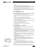
6. Install the six hex nuts to secure the lid in place. Tighten by hand, and then tighten
with an extra 1/2 to 1 turn. Caution! Over-tightening these nuts will cause the lid to
warp and possibly leak fumes or flames.
7. Re-install the igniter. Tighten the screws by hand, and then tighten with an extra 1/8 of
a turn.
8. Re-attach the igniter wire to the igniter.
3.4.2 Removing the burner
3.4.2.1 Removing the burner - SL 10-85 G3, SL 14-115 G3, SL 20-160 G3
1. Turn off the power and the gas supply to the boiler.
2. Remove the front cover, and allow the boiler to cool down to the surrounding
temperature.
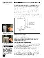
3. Remove the 8 Torx screws around the fan coupler, and lift off the fan coupler carefully.
Note:
The fan coupler seals against the heat exchanger lid with a high temperature
silicone O-ring. If the O-ring is damaged in any way it must be replaced.
4. Carefully pull the burner straight up. The burner is sealed to the heat exchanger
lid with a graphite gasket. If the graphite gasket is damaged in any way it must be
replaced.
3.4.2.2 Removing the burner - SL 30-199 G3
1. Turn off the power and the gas supply to the boiler.
2. Remove the front cover, and allow the boiler to cool down to the surrounding
temperature.
3. Disconnect the igniter cable.
4. Remove the two screws that secure the igniter to the lid using a # 15 TORX
screwdriver.
5. Carefully remove the igniter by sliding it straight up.
6. Remove the igniter gasket, and place the parts on a clean dry area.
7. Remove the two screws that attach the fan to the heat exchanger lid.
8. Remove the 8 hex nuts that attach the heat exchanger lid to the heat exchanger with
a 10 mm open-end wrench or socket.
9. With a permanent marker or equivalent, make an alignment mark between the lid,
gasket, and heat exchanger.
10. Before removing the lid, it is important to be positioned directly above it to ensure a
straight-up extraction. Failing to do this may result in refractory damage.
11. Slowly lift the lid-burner assembly off the heat exchanger. The refractory should
remain in place in the combustion chamber shoulder. Note that there is less than
1/8” (3 mm) clearance between the burner walls and the refractory. Care must
be observed to ensure minimal contact between these parts to prevent refractory
Summary of Contents for SL 20-160 G3
Page 75: ...6 3 DIAGRAMS SL 10 85 G3 SL 14 115 G3 SL 20 160 G3 SL 30 199 G3 MODULATING GAS BOILERS...
Page 77: ...6 5 DIAGRAMS SL 10 85 G3 SL 14 115 G3 SL 20 160 G3 SL 30 199 G3 MODULATING GAS BOILERS...
Page 79: ...6 7 DIAGRAMS SL 10 85 G3 SL 14 115 G3 SL 20 160 G3 SL 30 199 G3 MODULATING GAS BOILERS...
Page 85: ...SERVICE RECORD DATE LICENSED CONTRACTOR DESCRIPTION OF WORK DONE...
Page 86: ...NOTES...
Page 87: ...NOTES...


