INSTALLATION AND OPERATION INSTRUCTIONS
1-6
SL 10-85 G3, SL 14-115 G3, SL 20-160 G3, SL 30-199 G3 MODULATING GAS BOILERS
SL 10-85 G3, SL 14-115 G3, SL 20-160 G3, SL 30-199 G3 MODULATING GAS BOILERS
1.4.1 Applications
All SL series boilers are approved with alternative venting options: either 2-pipe Direct
Vent or Vent pipe with Indoor Air, offering flexibility to meet the specific requirements of
the installation. With the Direct Vent case, combustion air is piped directly to the boiler’s
air intake from outdoors
(see Section 1.4.7 for air intake piping requirements).
Using the
indoor air alternative, air for combustion is drawn from the indoor air surrounding the
boiler.
Provided the maximum overall vent length limit is not exceeded, the installer may choose
to vent the boiler through the wall, directly through the roof or upward using an existing,
but otherwise unused, chimney
as a vent raceway.
1.4.2 Exhaust Vent Material
Exhaust Vent Material – CANADA
Use PVC, CPVC or Polypropylene (PPs) vent component systems approved under
ULC-S636 Standard for Type BH Gas Venting Systems, or stainless steel Type BH venting
systems*. The vent temperature is limited with the use of a flue temperature sensor
and software to ensure the maximum temperature of the PVC venting material is not
exceeded.
Exhaust Vent Material – USA
PVC, CPVC or PPs venting materials are approved for use with these boilers in the USA.
The vent temperature is limited with the use of flue temperature sensor and software to
ensure that the maximum temperature of the PVC venting material is not exceeded. PVC
venting material shall be certified to Sch. 40 ASTM D1785 or D2665. CPVC material shall
be certified to Sch. 40/ASTM F441.
Exhaust Vent Material - OTHER COUNTRIES
Do not use ABS or any cellular core pipe for exhaust venting.
Use of cellular core PVC (ASTM F891), cellular core CPVC, or Radel®
(polyphenolsulfone) in venting systems shall be prohibited.
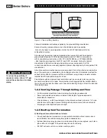
The boiler offers 3” venting connections. Fittings are to be used to adapt to the appropriate
diameter
(see Vent Travel below)
. There are two stainless steel, gasketed fittings on the
top of the boiler. Exhaust venting is to be inserted directly into the 3” female stainless steel
fitting on the left
(see Figure 4).
For PPs material, use the 3” transition/ adaptor fitting (Sch 40 to PPs) offered by the
respective PPs manufacturers Centrotherm /
Innoflue
TM
(their part # ISAA0303) or M&G
Dura Vent /PolyPro (#3PPS-AD) or Z-Flex/Z_DENS (#2ZDCPVCG3). For 2” venting, use
Innoflue part # ISRD0302 or
PolyPro
# 3PPS-R2 (within the PPs piping, after adapting
with #3PPS-AD) or Z-DENS #2ZDR32 (within the PPs piping, after adapting with
#2ZDCPVCG3). For PPs material exposed to outdoor weather, follow the venting suppliers’
recommendations on UV protection.
Combustion air piping - if used - is inserted directly into the 3” female stainless steel fitting
on the right
(see Section 1.4.7).
Venting shall be supported in accordance with the applicable code.
*
Manufacturers of stainless steel Type BH venting systems must submit their approved
transition fitting to IBC for evaluation and written approval.
WARNING
Covering non-metallic vent
pipe and fittings with thermal
insulation shall be prohibited.
Summary of Contents for SL 20-160 G3
Page 75: ...6 3 DIAGRAMS SL 10 85 G3 SL 14 115 G3 SL 20 160 G3 SL 30 199 G3 MODULATING GAS BOILERS...
Page 77: ...6 5 DIAGRAMS SL 10 85 G3 SL 14 115 G3 SL 20 160 G3 SL 30 199 G3 MODULATING GAS BOILERS...
Page 79: ...6 7 DIAGRAMS SL 10 85 G3 SL 14 115 G3 SL 20 160 G3 SL 30 199 G3 MODULATING GAS BOILERS...
Page 85: ...SERVICE RECORD DATE LICENSED CONTRACTOR DESCRIPTION OF WORK DONE...
Page 86: ...NOTES...
Page 87: ...NOTES...


