IBC Technologies Inc.
19
VFC 15-150 and VFC 45-225
1.6 Gas
Piping
The boiler requires an inlet gas pressure
of at least 3.0” w.c. for natural gas or
propane. For either fuel, the inlet
pressure shall be no greater than 14.0”
w.c. Confirm this pressure range is
available with your local gas supplier.
The inlet gas connection of the boiler’s
gas valve is 1/2” NPT (female).
Adequate gas supply piping shall be
provided with no smaller than 1/2” Iron
Pipe Size (IPS), in accordance with the
following chart:
Table 5 - Max. Pipe Length (ft)
Model
1/2” IPS
3/4” IPS
1” IPS
VFC 15-150 (Nat gas)
10 40 130
VFC 15-150 (Propane)
50 180 620
VFC 45-225 (Nat gas)
5 20 60
VFC 45-225 (Propane)
25 90 290
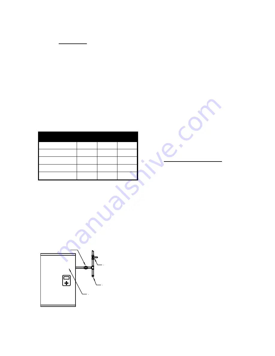
Gas piping must have a sediment trap
ahead of the boiler’s gas valve (see
Figure 10
.). A manual shutoff valve
must be located outside the boiler, in
accordance with local codes/standards.
All threaded joints in gas piping should
be made with a piping compound
resistant to the action of natural gas. Use
proper hangers to support gas supply
piping.
UNION
INSTALL MANUAL
MAIN SHUTOFF
VALVE 5 FT.
ABOVE FLOOR
WHEN REQUIRED
BY LOCAL CODE
FULL SIZE
SEDIMENT
TRAP
GAS VALVE INSIDE
Figure 10. Typical Gas Piping
The boiler must be disconnected or
otherwise isolated from the gas supply
during any pressure testing of the system
at test pressures in excess of 1/2 psig.
Dissipate test pressure prior to
reconnecting. The boiler and its gas
piping shall be leak tested before being
placed into operation.
The gas valve is provided with pressure
taps to measure gas pressure upstream
(supply pressure) and downstream
(manifold pressure) of the gas valve –
see Figure 12, page 37. Note that
manifold pressures vary in accordance
with firing rate with the modulating
series boilers.
1.7 Electrical
Connections
All Electrical wiring to the boiler
(including grounding) must conform to
local electrical codes and/or National
Electrical Code, ANS/NFPA No. 70 –
latest edition, or The Canadian Electrical
Code, C22.1 - Part 1.
1.7.1 “110V” Hook-up
Line-voltage wiring is done within the
field-wiring box. Referring to
Wiring
Diagram
on page 53, connect the boiler
to the grid power using a separate, fused
circuit and on/off switch within sight of
the boiler. Use 14-gauge wire in BX
cable or conduit appropriately anchored
to the boiler case for both mains supply
and pump circuits.
Connect a 120 VAC / 15 amp supply to
the “
AC in
” tagged leads within the
wiring box. The maximum actual draw
(including 4 typical residential size
pumps) is less than 4 amps.
If primary / secondary piping is used,
with pumps to manage multiple loads,


