IBC Technologies Inc.
11
VFC 15-150 and VFC 45-225
1.4.1.6
Sidewall Vent Termination
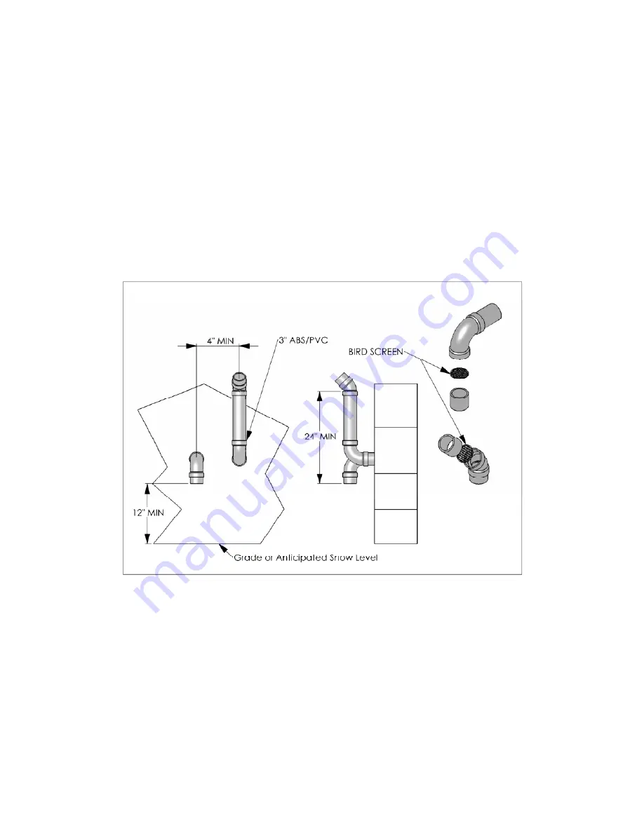
Sidewall direct vent applications shall be
vented as follows:
•
both the inlet and exhaust
terminations should normally be
located on the same plane (side) of
the building,
•
the exhaust outlet is to be placed so
as to reach 24” minimum above the
down-turned intake - to avoid
exhaust re-ingestion.
•
The elevation of both pipes can be
raised in “periscope style” after
passing through the wall, then
configured as above, to gain
required clearance.
•
Use a 45° elbow on the exhaust
termination to launch the plume up
and off the sidewall, for protection
of wall.
•
bird screen of ¼” stainless steel or
plastic mesh is useful to guard
against foreign objects
Figure 4 - Sidewall Vent Termination - Piping Configuration
To promote the projection of exhaust away from the building and from the intake pipe,
reduction of 3” pipe to 2” is permitted for a maximum lineal travel of 3’ including 2 x
90° elbows on each side. This allows for smaller wall penetrations, with sufficient travel
allowance to achieve the minimum exterior configuration as shown above.
For side venting of multiple boiler sets, group all intake terminals together with 4” to 8”
lateral spacing, and similarly group the exhaust pipes. Place the 2 groups on the same
plane of the building (e.g. north facing wall(s)). Place the 2 groups of pipes at least 3’
apart (the closest intake and exhaust pipes shall be 36” - or more – apart. Use same 24”
(minimum) vertical separation as displayed above.


