


59
/
3. Operation
[3]
Pause during Movement (For Single Solenoid System) ••• PIO Pattern 0 to 2
* Inputting the STP signal pauses the actuator motion. A forward position movement example is
shows as follows.
Positioning Band
(Parameter No. 1)
Pause
Forward Position
[4]
Pause during Movement (For Double Solenoid System) ••• PIO Pattern 0 to 2
The actuator motion is paused by means of tuning OFF both of ST0 and ST1. The following
fi
gure shows an example of forward position movement.
Positioning Band
(Parameter No. 1)
Pause
Forward Position
ST0 and ST1 are off
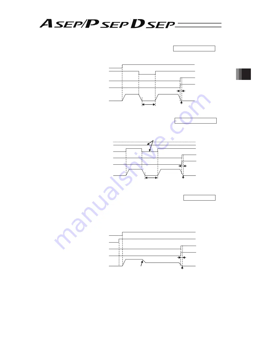
[5]
Speed Change during the Movement (For Single Solenoid System) ••• PIO Pattern 1
The movement speed is changed during the actuator’s movement to the target position. When
the movement command is issued with SPDC turned ON, the actuator is moved at the changed
speed speci
fi
ed using the Speed Change function from the position set for the speed change
in the position setting operation. The following figure shows an example of forward position
movement.
Position Set as the Change Position
Positioning Band
(Parameter No. 1)
Forward Position
Movement Signal (ST0)
Pause Signal (*STP)
Forward Position Detection Output (LS1)
Forward Positioning Completion Output (PE1)
Actuator Operation
Backward Position Movement Signal (ST0)
Forward Position Movement Signal (ST1)
Forward Position Detection Output (LS1)
Forward Positioning Completion Output (PE1)
Actuator Operation
Movement Signal (ST0)
Movement Speed Change Signal (SPDC)
Forward Position Detection Output (LS1)
Forward Positioning Completion Output (PE1)
Actuator Operation
Summary of Contents for ASEP
Page 1: ...DSEP Controller ASEP Controller PSEP Controller Instruction Manual Tenth Edition ...
Page 2: ......
Page 4: ... ...
Page 115: ......