background image

12

The 

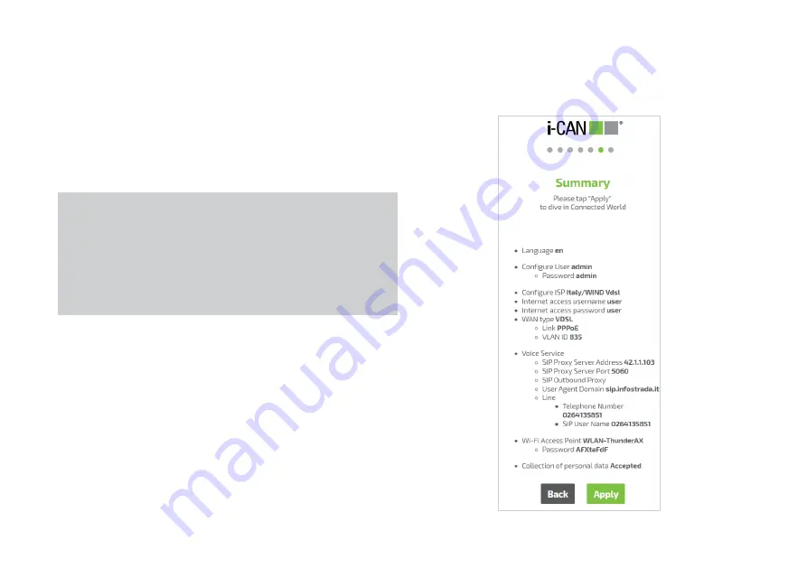
Summary

 page will be shown listing all device settings 

specified during the procedure (see Figure 7).

Click 

Back

 to revisit the previous steps if any setting needs to be 

changed or 

Apply

 to confirm the configuration.

Figure 7. First Configuration Wizard - Summary


ƒ

NOTE:

Applying the configuration, router will connect to Internet 
using inserted parameters. If WAN interface failure occurs, 
the router will provide the skip option and will redirect to 
router’s homepage for manual configuration. Router’s GUI 
allows to configure WAN connection manually or to restart 
the Wizard process. (refer to figure 13)

Step 7 - Summary

Summary of Contents for Thunder AX 3600

Page 1: ......

Page 2: ...igured in accordance with the user guide The product shall be used and installed indoor with a maximum ambient temperature of 40 C The product shall be installed in a place with a grade 2 of environmental pollution a place without conducting polluting agents The product shall not be placed near any source of heat or direct sunlight The product shall be placed in a well ventilated area in order to ...

Page 3: ...NPACKING YOUR WI FI 6 ULTRA FAST HOME GATEWAY Thunder Wi Fi 6 Ultra Fast Home Gateway Power Supply DSL Splitter Grey DSL Cable Yellow Ethernet Cable Red Ethernet Cable Safety Flyer Quck Installation Guide ...

Page 4: ...ECTIONS Camera USB Key Printer HDD USB POWER SUPPLY ETHERNET PHONES INTERNET DUAL BAND WI FI or Gaming console Tablet Smartphone Notebook DSL Fiber VoIP Analogue PC TV Gaming console NAS Printer 2 4 GHz 5 GHz ...

Page 5: ...nguage Step 2 Login and Password configuration Step 3 Entering the information for establishing a connection to the Internet as determined by the Internet Service Provider ISP Step 4 Configuring Voice over IP Service optional Step 5 Assigning a name and a passphrase to secure the Wi Fi home network optional Step 6 Personal Data Collection optional Step 7 Summary Step 8 Firmware Upgrade automatic C...

Page 6: ...ge 1 Click ARROW DOWN next to the language name to display the list of available languages 2 Click to select a language from the drop down menu The page refreshes with the selected language Click Start to initiate the setup process Figure 1 First Configuration Wizard Language Selection Step 1 Selecting a Language ...

Page 7: ...the specified login name 3 Retype the password When all the required information has been specified the button Next becomes active allowing to proceed to Wizard Step 3 Click Back to return to the previous Step or Next to continue configuring the router Figure 2 First Configuration Wizard User Configuration NOTE This information enables users to enter router s full configuration Please make sure to...

Page 8: ...ed according to the documentation that should have been provided by or could be obtained from the ISP Click Back to return to the previous Step or Next to continue configuring the router If this step is taken again at a later time from the Internet configuration page Section 3 2 or by restarting the Wizard from the Menu in the Home page see Section 4 6 it would be possible to click Skip to skip th...

Page 9: ...cription Click Back to return to the previous Step Skip to skip this step or Next to continue setting up the device If this step is skipped it would be possible to complete the configuration of the VoIP service at a later time from the VoIP configuration page Section 3 5 or by restarting the Wizard from the Menu in the Home page see Section 4 6 Figure 4 First Configuration Wizard Voice Service Ste...

Page 10: ...guration can be completed later on from the Wi Fi con figuration page Section 3 3 or by restarting the Wizard from the Menu in the Home page see Section 4 6 The Back button can be clicked to return to the previous Step Figure 5 First Configuration Wizard Wi Fi Access Point NOTE If the Wizard is run at first device switch on or after a reset to device factory configuration the SSID and password wil...

Page 11: ...ta from the router to management system if needed Data collection acceptance is optional users can accept enabling button in the menu or discard Click Back to return to the previous Step or Next to continue configuring the router Figure 6 First Configuration Wizard Personal Data Step 6 Personal Data Collection ...

Page 12: ...configuration Figure 7 First Configuration Wizard Summary NOTE Applying the configuration router will connect to Internet using inserted parameters If WAN interface failure occurs the router will provide the skip option and will redirect to router s homepage for manual configuration Router s GUI allows to configure WAN connection manually or to restart the Wizard process refer to figure 13 Step 7 ...

Page 13: ...dure Upgrading router to the latest available software release takes place from the page illustrated in Figure 8 The page shows the following information 1 New firmware is available 2 Current firmware version Click Upgrade to start the automatic installation of new soft ware or Retry to check for a newer firmware version again Figure 8 First Configuration Wizard Firmware Upgrade NOTE If new firmwa...

Page 14: ...essful application of all configuration parameters the Wizard will close and the Home page will be displayed see Figure 9 A detailed description of the Home page content is provided in Section 3 Figure 9 Home page ...

Page 15: ...er s IP address default http 192 168 1 1 or router name i can thunder in the browser address field see Figure 10 5 The Login page will show up see Figure 11 6 Enter the router login name created during Configuration Wizard Step 2 e g admin 7 Enter the password for the specified login name created during Configuration Wizard Step 2 8 Optionally change the display language using the relevant dropdow...

Page 16: ...lly terminated after a predefined inactivity timeout The Login page will be shown again to allow for user re authentication Upon successful login the Home page is displayed The Home screen provides a complete overview of the router s status and configuration settings ...

Page 17: ...er of items corresponding to actions that can be performed on the device or the device configuration pages namely Logout button see Section 3 1 GUI Language choice see Section 3 2 Restore default settings see Section 3 3 Change password see Section 3 4 Reboot see Section 3 5 Wizard see Section 3 6 Firmware Upgrade see Section 3 7 Figure 13 Menu ...

Page 18: ...18 3 1 Logout The Logout button Figure 14 allows to log out from the ongo ing GUI session 1 Click on the Menu icon in the Home page to display the Menu 2 Click the Logout button Figure 14 Logout button ...

Page 19: ...e used in the GUI To change the current language 1 Click on the Menu icon in the Home page to display the Menu 2 Click the ARROW DOWN icon next to the language name to display the language drop down menu see Figure 15 3 Select a language from the menu 4 The page refreshes with the chosen language ...

Page 20: ...con in the Home page to display the Menu 2 Click Restore Default Settings menu entry a page will ap pear displaying a warning message see Figure 16 3 Click the Restore button to confirm The process starts 4 When factory settings are successfully restored the user will be automatically reconnected to the router If the operation fails the user will be asked to log in again WARNING This action will c...

Page 21: ...re 17 3 Enter the current password 4 Enter the new password 5 Retype the new password 6 If the same set of characters has been entered at steps 4 and 5 the Apply button becomes active and can be clicked to operate the password change Figure 17 Change Password panel NOTE The panel includes suggestions for choosing a secure password and reports a visual indication about the security grade of the one...

Page 22: ...e Home page to display the Menu 2 Click Reboot menu entry a page will appear displaying a notification about the reboot process see Figure 18 3 Click the Reboot button the reboot progress pop up see Figure 23 will be shown until the operation completes 4 When reboot terminates the Login page will be automati cally displayed in the same browser window ...

Page 23: ...1 NOTE The value displayed for the various configuration parameters that can be set in Wizard pages is the one currently applied When the Wizard is run for the first time this will correspond to the value set as factory default For all successive Wizard execution the value shown is the one set beforehand ...

Page 24: ...l appear displaying the version of the currently installed firmware and asking to select the file containing the new image 3 Click Select File a file browser windows will appear through which it will be possible to navigate to the folder containing the new firmware image file and select it for upload 4 Click the Upload button 5 If the file is correctly transferred and contains a valid firm ware im...

Page 25: ...mmary with list of Model name Firmware Version Serial Number MAC Address Uptime Internet see Section 4 2 for more information Connection profile Status of the connection Uplink and Downlink speed Wi Fi see Section 4 3 for more information Radio switch on switch off toggle Network name SSID Number of currently connected devices WPS function 04 Wi Fi Guest see Section 4 4 for more information Radio ...

Page 26: ...8 for more information Security see Section 4 9 for more information Diagnostic see Section 4 10 for more information When clicked the Menu icon shown in the Home page upper left corner see section 3 opens a list box containing a number of actions including e g session logout language selec tion password change router reboot Wizard configuration firmware upgrade see Figure 13 More information abou...

Page 27: ...but still visible on the screen sides Clicking any where on the dimmed area will bring the Home page back the same effect can also be achieved by clicking ARROW LEFT at the top left corner of the page Tile specific pages are organized in two panes the one on the left listing the main page sections and the one on the right re porting status information and or settings for the functionalities repres...

Page 28: ...ill be displayed asking to confirm this action contextually offering the possibility of reenter the configuration page see Figure 22 Some configuration changes require the router to be rebooted in this case a warning page will pop up See Figure 23 notify ing the need for such action and asking for a confirmation to proceed During reboot a progress bar will be shown with the indication of the appro...

Page 29: ...ng the current Uplink and Download speed The Internet page see Figure 25 opens when clicking the Internet tile in the Home page see Section 3 The page left panel lists five sections namely Physical Link xDSL IP Link IP Link Advanced Configuration whose relevant details are expanded in the page right panel Note that clicking More settings in the IP Link section in the right panel has the same effec...

Page 30: ...is reported If no link is active Active Link indi cates Not configured and a link is shown leading to a Troubleshooting page Connection Time How long the Internet connection physical layer has been in the Up status Physical Link Speed The bitrate measured at physical layer in the Uplink to the Internet and Downlink from the Internet directions More settings Additionally technology specific details...

Page 31: ...en Status is Up the public IP address assigned to the router by the Internet Service Provider Bandwidth in use Currently used link bandwidth in Uplink Up and Downlink Down directions Data transferred Data transferred in Uplink and Downlink direc tions since last router switch on More settings Additional details about the IP link status see Figure 29 These are listed in Default Gateway IP Address a...

Page 32: ...32 Figure 30 Internet Disconnected If there is no Internet connection additional menu entries will be shown Troubleshooting see Figure 30 Click it to go directly to the Troubleshooting section ...

Page 33: ...der but ton use the WPS button to trigger the WPS Wi Fi Protected Setup process used for associating a wireless client to the router without the need of entering the Wi Fi password on the client this has the same effect as pressing the physical button on the router Wi Fi Guest tile allows performing basic actions on the wireless network specifically enable disable Wi Fi connection via the ON OFF s...

Page 34: ...r applied to both bands choosing Separate mode causes both Access and Settings sections to split in two parts where status and configura tion parameters are separately presented for the two bands Enabled ON OFF slider button Enables or disables the wireless network one or both bands depending on the selected mode Network Name SSID Displays modifies the name of the wireless network one or both band...

Page 35: ...solation ON OFF slider button When set to OFF wireless clients can see each other as well as other devices in the Home Network and mutually exchange data when set to ON each wireless client can only connect to the Internet Security Mode drop down menu Displays and allows to change the Wi Fi security mode When clicking ARROW DOWN the following op tions are shown None no security WPA2 Personal prefe...

Page 36: ...ually selected by the user Channel Displays and allows to change the Wi Fi radio channel in use in each band see Figure 35 The options shown when clicking ARROW DOWN depend on band 2 4 GHz or 5 GHz 2 4 GHz Auto 1 13 5 GHz Auto 36 40 44 48 The Auto option lets the router auto matically select the best channel based on a survey of the radio environment In Common mode the only allowed choice is Auto ...

Page 37: ... change the band width of the Wi Fi radio channel in use by each network The options shown when clicking ARROW DOWN depend on the router model and the network band 2 4 GHz or 5 GHz 2 4 GHz Auto 20 40 5 GHz Auto 20 40 80 160 The Auto option lets the router automati cally select the best bandwidth Auto is the only option available in Common mode Furthermore in Sepa rate mode options different from A...

Page 38: ...outer wireless network name SSID number of connected devices Wi Fi Guest tile allows performing basic actions on the wireless network specifically enable disable Wi Fi connection via the ON OFF slider but ton To bring up more details about the Wi Fi connection click on the Wi Fi Guest tile A Wi Fi detailed view page will be displayed Figure 31 allowing to configure Wi Fi parameters ...

Page 39: ...ented or applied to both bands choosing Separate mode causes both Access and Settings sections to split in two parts where status and configuration parameters are sepa rately presented for the two bands Enabled ON OFF slider button Enables or disables the wireless network one or both bands depending on the selected mode Network Name SSID Displays modifies the name of the wire less network one or b...

Page 40: ...er button When set to OFF wireless clients can see each other as well as other devices in the Home Network and mutually exchange data when set to ON each wireless client can only connect to the Internet Security Mode drop down menu Displays and allows to change the Wi Fi security mode When clicking ARROW DOWN the following op tions are shown None no security WPA2 Personal preferred and WPA WPA2 Pe...

Page 41: ...s four sections namely IP Settings DHCP Settings Dynamic DNS Static Hosts Devices USB Devices whose relevant details are expanded in the page right pane Note that clicking More settings in the IP Settings section in the right panel will display the same information shown when click ing DHCP Settings or Dynamic DNS Information reported for each section is described below WARNING Default values of p...

Page 42: ...rver used to automatically assign IP addresses to Home Network devices IP Address Pool Displays and allows to change the range of IP addresses that will be assigned by the DHCP Server to devices in the Home Network The range is defined by addresses specified for the Start IP and End IP parameters both of which must be within the subnet specified by IP Address and Subnet Mask Domain Name Displays a...

Page 43: ...namic DNS DDNS A DDNS provider maintains upon subscription an association between the router s public ad dress and a hostname in the domain name system This allows the router and clients in the Home Network to be reachable from the Internet using URLs in that domain instead of their IP address Provider drop down menu Displays and allows to change the name of the DDNS provider click ARROW DOWN to d...

Page 44: ...ays the Re serve IP Address view Figure 42 which shows the list of clients for which an address reservation has been done each entry includes the client name if defined or Un known host otherwise its MAC address and the assigned IP address Click Add New to enter the Add New Static IP view Figure 43 for adding an ad dress reservation for a new client In the Add New Static IP view click the Select D...

Page 45: ... card Figure 44 that displays the device MAC address and using ARROW RIGHT allows changing its previously assigned IP address clicking Unselect will revert the previous view To make a reservation for a device which is not listed click Enter MAC Address at the bottom of the drop down list A card is then displayed Figure 45 where both the MAC address and the reserved IP address can be specified Clic...

Page 46: ...hically shows the type of device and type of connection with the router Different device types and link technologies are indicated with specific icons and line styles respectively The meaning of icons and line styles is shown by clicking in the screen bottom right Clicking will display the map in full screen mode In full screen mode clicking or Home Network ARROW LEFT in the screen top left will r...

Page 47: ... part that shows those currently connected to the router as done in Map tab and a second part Off line which shows devices that have been connected to the router in the past but which are currently disconnected Each entry in the list includes the device name if known to the router or Unknown host otherwise and its IP address ...

Page 48: ...ice Details card Figure 48 that shows a number of device specific parameters The card will also allow to reserve the IP address shown for the device through the Reserve IP address ON OFF slider button as a shortcut to what can be done in the Static Hosts section using the procedure described above ...

Page 49: ...connected to USB port s on the router Clicking on the icon or the name of an individual USB Device will open the tab with the Device Details Figure 50 showing the type of connection of the device to the router its current status the name of the device and its capacity Figure 50 USB Device Details ...

Page 50: ...1 Clicking the Telephony tile in the Home page takes to the VoIP configuration section see Figure 51 Phone Lines section Enabled ON OFF slider button Enables or disables the VoIP service that it has been previously configured via the configuration Wizard Number The telephone number registered for the service Status The status of the VoIP line Up if ac tive Disabled if not active Calls List Clickin...

Page 51: ...51 Figure 52 Call List details ...

Page 52: ... details WARNING VoIP configuration parameters depend on your VoIP provider data to be received on VoIP service activation Default values of parameters in Telephony sections should be left unchanged if VoIP concepts are not well understood TAB DESIGNATION Telephony lines Adding and configuring telephony num bers Voice Profile Configuring line parameters and SIP Service Settings Configuring call se...

Page 53: ...the Internet and the Home Network Clicking on the DSL tile takes to the status page of the DSL interface see Figure 55 Other action on this page that allows to select may include Ethernet WAN link Figure 56 Ethernet LAN link Figure 56 Internet Figure 57 VoIP Figure 58 Wi Fi 5 GHz network Figure 59 Wi Fi 2 4 GHz network Figure 60 Figure 56 Interfaces Ethernet WAN status page ...

Page 54: ...54 Figure 57 Interfaces Internet status page Figure 59 Interfaces Wi Fi 5 GHz status page Figure 58 Interfaces VoIP status page Figure 60 Interfaces Wi Fi 2 4 GHz status page ...

Page 55: ...ing review filter and change settings for system logs collected by the device Figure 62 Reboot see Figure 63 Factory Reset see Figure 64 Backup Configuration file see Figure 65 Load Configuration see Figure 66 Firmware upgrade see 67 Date Time Network Time Setting see Figure 68 DLNA Media Sharing see Figure 69 USB Sharing configuration of USB devices see 70 ...

Page 56: ...56 Figure 62 Logging log page Figure 63 Reboot Figure 64 Factory Reset Figure 65 Backup Configuration ...

Page 57: ...57 Figure 66 Load Configuration Figure 67 Firmware Upgrade Figure 68 Date Time Figure 69 DLNA ...

Page 58: ...slider button Enables or disables File Sharing service Netbios Name Allows to set the name of the storage device as will be seen by clients in the Home Network Work Group Allows to specify the name of the Work Group which the storage device will be as signed to Home Network devices belong ing to the same Work Group will be able to discover and access the device through Windows File Explorer or any...

Page 59: ... control application you might need PIN code from administrator VPN see Figure 75 Configure VPN Client and Server VPN IPSec configuration manual or automatic via available wizard Remote Gateway Road Warrior Mikrotik Cisco Port Mapping see Figure 76 Configure router Port map ping for known or custom Applications Routing QoS see Figure 77 Clicking tile takes to the page with set of additional Menu R...

Page 60: ...60 Figure 72 Firewall settings page Figure 74 Parental Control access page Figure 73 DMZ settings page Figure 75 VPN type selection ...

Page 61: ...61 Figure 76 Port Mapping Figure 78 User Figure 77 Routing QoS Figure 79 Management ...

Page 62: ... allowing you to launch a diagnostic tool dow upl for displaying speed and state of WAN access across an Internet Protocol IP network Traceroute tool see Figure 84 page allowing you to launch a diagnostic tool for displaying the path and measur ing transit delays of packets across an Internet Protocol IP network Interfaces Summary list see Figure 85 page allowing you to monitor and check details a...

Page 63: ...63 Figure 81 Ping Figure 82 Download Figure 83 Upload Figure 84 Traceroute ...

Page 64: ...64 Figure 85 Interfaces Summary page ...

Page 65: ...65 Figure 86 Active Connections ...

Page 66: ...symbol on the product or on its packaging indicates that this product must not be disposed of with your other household waste Instead it is your responsibility to dispose of your waste equipment by handing it over to a desig nated collection point for the recycling of waste electrical and electronic equipment or to return it to the dealer when purchasing a new appliance The separate collection and...

Reviews: