MAIN MOVING SYSTEM
2-44
DISASSEMBLY
1. Remove the timing belt train, front case, flywheel, cylinder
head assembly, and oil pan.
2. Remove the rear plate and rear oil seal.
3. Disconnect the connecting rod cap.
4. Remove the main bearing cap. (Arrange it in order)
5. Remove the crankshaft.
6. Disassemble the crankshaft position sensor wheel.
NOTE
Put an identification mark on the main bearing cap
to refer to the original position and direction.
INSPECTION
1. Crankshaft
1) Check the oil hoe for clogging as well as crankshaft
journal pin for damage, uneven wear and crack. Repair
or replace parts if necessary.
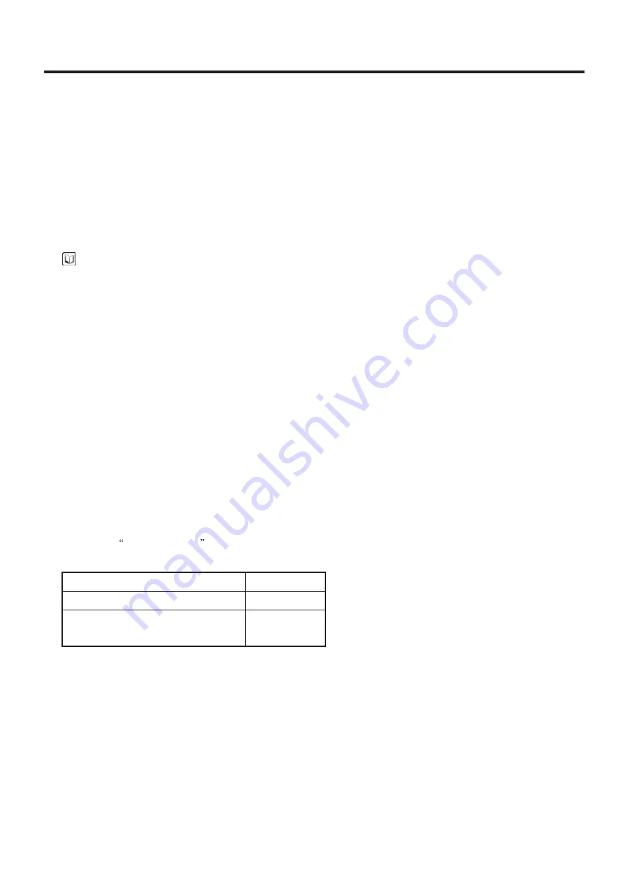
2) Inspect
out of circularity
of the crankshaft journal
taper and pin.
2. Main bearing and connecting rod bearing
Visually inspect each bearing for scratch, melting, sticking,
and fault contact and replace the bearing if necessary.
Crankshaft journal O.D
Crank pin O.D
57mm
45mm
0.01mm or less
Out of circularity of crankshaft journal
pin
Summary of Contents for 20G-7
Page 1: ......
Page 2: ......
Page 3: ......
Page 6: ......
Page 41: ...2 7 Mast Refer to the chapter 1 MAST Page 2 2 1 2 POWER TRAIN ASSEMBLY REMOVAL 1 D503RE04 ...
Page 59: ...3 7 OPERATING MODES Forward INPUT OUTPUT 4 1 INPUT OUTPUT 20D7PT29 20D7PT30 Reverse 2 ...
Page 231: ...7 3 FUEL SYSTEM CIRCUIT TIER 3 LPG 20L7EL07 ...
Page 232: ...7 4 FUEL SYSTEM CIRCUIT TIER 3 BI FUEL 20L7EL06 ...
Page 233: ...7 5 FUEL SYSTEM CIRCUIT NON CERT LPG 20L7EL08 ...
Page 234: ...7 6 FUEL SYSTEM CIRCUIT NON CERT BI FUEL 20L7EL09 ...
Page 235: ...7 7 MEMORANDUM ...
Page 267: ...MODEL L4GC SHOP MANUAL FOR INDUSTRIAL USE ...
Page 284: ...GENERAL 2 1 GENERAL OUTLINE L4GC001A ...
Page 285: ...GENERAL 2 2 L4GC002A ...
Page 346: ...LUBRICATION SYSTEM 2 63 4 Front case Oil pump 5 Timing belt 6 Timing belt cover ...
Page 390: ...3 21 5 Loosen 4 through bolts L4GC330A L4GC048A 6 Separate the rotor and cover CHARGINGSYSTEM ...
Page 402: ...1 GENERAL 4 1 2 INJECTOR 4 14 4 PVC VALVE 4 16 CHAPTER 4 FULE SYSTEM AND OTHER ...
Page 420: ......


