background image

English – 

29 

Basic dismantle/assembly

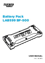
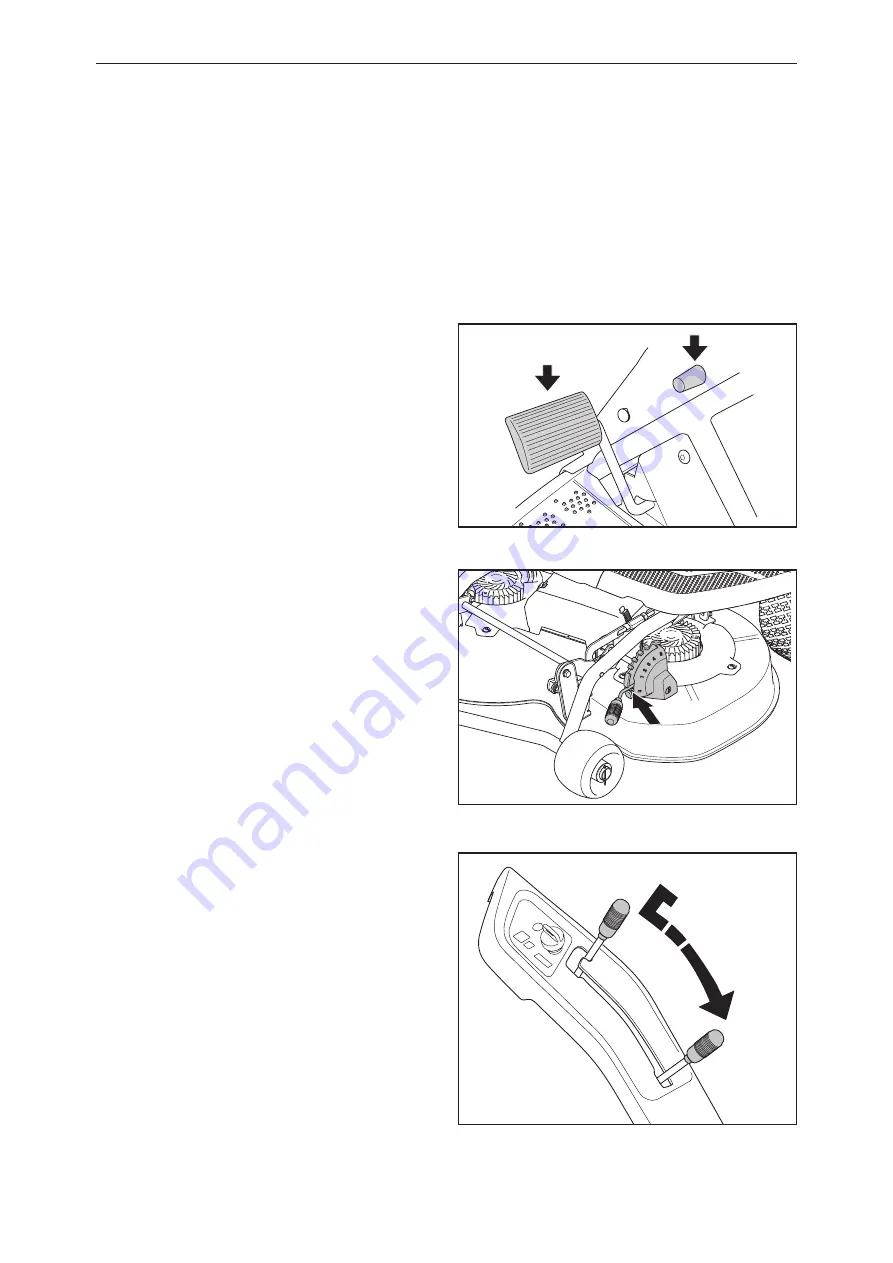
6.6 Removing the Cutting Deck

To dismantle the cutting deck proceed as follows:

1

Put the machine in a level position.

2

Turn off the machine and remove the ignition key.

3

Apply and secure the parking brake.

4

Check that the lever for setting the cutting height is 

in the S position.

5

Lower the cutting unit.

Summary of Contents for 967187001

Page 1: ...Workshop manual Rider Battery English ...

Page 2: ......

Page 3: ...products without prior notice 1 Index 4 2 Introduction and Safety Regulations 7 3 Special Tools 11 4 Technical Data 14 5 Design and Function 15 6 Basic Dismantle Assembly 19 7 Repair Work 33 8 Repair Work Electrical Components 64 9 Troubleshooting with Common Service Tool 77 10 Description of Electrical System 81 11 CST Autotest 97 12 CST Drive Mode Logging 115 13 Manual CST Tests 125 14 Batteries...

Page 4: ...ade Motor 45 7 13 Loosen the Pedal Plate 48 7 14 Changing Microswitch P brake 52 7 15 Changing Microswitch Reverse Drive 53 7 16 Changing Microswitch Forward Drive 54 7 17 Changing Speed Potentiometer 56 7 18 Changing Recoil Spring in Pedal Plate 57 7 19 Calibrating Speed Potentiometer 59 7 20 Calibrating Speed 60 7 21 Assemble New Baffle Plate 61 7 22 Changing Microswitch Baffle Plate 63 8 Repair...

Page 5: ...avE LED on 131 13 13 Test Error LED on 132 13 14 Battery LEDs 132 13 15 Battery 100 LED on 132 13 16 Battery 75 LED on 133 13 17 Battery 50 LED on 133 13 18 Battery 25 LED on 134 13 19 Battery Low LED on 134 13 20 Keypad Buttons 135 13 21 Activation 135 13 22 SavE 135 13 23 Miscellaneous 136 13 24 Charger Status 136 14 Batteries and Maintenance 137 14 1 Battery Maintenance 138 14 2 Measures when R...

Page 6: ...ledger Enter any revisions and corrections to the workshop manual into the table below Revision can be notified by Husqvarna AB as service information or the equivalent Enter the service notes into the troubleshooting software Common Service Tool CST ...

Page 7: ...be read together with all service information concerning the Rider in question 2 5 Tools Special tools are required for some stages All service tools are listed in the Workshop Manual Usage is made evident in each section 2 6 Parts and Accessories Always use original Husqvarna Spare parts Service tools Accessories or you may invalidate the warranty and risk your personal safety 2 7 Structure This ...

Page 8: ... feet Clutch in Clutch out Parking brake Noise emissions to surroundings in accordance with the European Union s directive The machine s emissions are set out in the chapter Technical data and on the decal Rotating blades Keep hands and feet away from under the hood when the engine is running Never drive directly across a slope Never use the ride on mower if persons especially children or pets are...

Page 9: ...ns In the event of spillage on the skin wash immediately with water Acid in eyes can result in blindness seek medical aid Be careful when servicing the battery Explosive gases are formed in the battery Never carry out service on the battery while smoking or when in the vicinity of naked flames or sparks The battery can then explode and cause serious injury 2 11 Risk of Sparks WARNING Never short c...

Page 10: ...the machine when conducting some of the tests Observe great care during these procedures Power to the machine must also be disconnected when carrying out other work to reduce the risk of short circuits Remove covers to access the batteries see 6 2 Disconnect the cables from the positive terminals as illustrated below in order to ensure the machine is not live ...

Page 11: ...used when working on the ride on mower RPM TOT MEM DIGITAL TACHOMETER 535 41 32 02 Mandrel for assembling the bushings on the pendulum shaft 502 28 80 01 Tachometer 578 92 62 01 Adjustment tool for wheel speed USB type A to type B Included with Diagnostic Tool ...

Page 12: ...he object and the reflective tape The display will light up after 1 2 seconds 4 Hold in the measuring button during the whole measuring procedure The instrument is turned off when the measuring button is released Read the last highest and lowest values The instrument will automatically save the last highest and lowest readings for a measurement i e as long as the measuring button is depressed Pres...

Page 13: ...lish 13 Special Tools Hydrometer and refractometer DC DC Multimeter Clip on ammeter The voltage tester enables measurement of insulated cables by penetrating the cable sheath Battery fluid distilled water ...

Page 14: ...output kW 0 8 Motor speed rpm 3400 Electrical System Type 36 V negative grounded Main fuse front carriage 150 Main fuse rear carriage 150 Cutting deck fuse A 80 Charging fuse A 15 Key switch fuse A 5 Freewheel fuse A 30 Battery Type of battery Open lead acid Voltage V Ah 3x 12 V 125 Ah Weight kg pce 40 Noise emission and cutting width see note 1 Noise power level measured dB A 93 Noise power level...

Page 15: ...l CST see 9 1 Design and Function Tire pressure should be 60 kPa 0 6 bar 8 5 PSI on all wheels Highest permitted pressure is 130 kPa 1 3 bar 14 PSI IMPORTANT INFORMATION Differing pressures in the front wheels will result in uneven mowing 5 2 Wheels 5 Design and Function Table of contents 5 1 Administration 15 5 2 Wheels 15 5 3 Serial Number 16 5 4 Steering 17 5 5 Cutting Deck 18 5 6 Service Posit...

Page 16: ...esignation and serial number when ordering spare parts The engine s serial number is given on a bar code decal 2 It is placed on one end of the motor The text gives Part no Serial no Please provide the engine model and serial number when ordering spare parts Husqvarna AB Model PNC ML Serial Number Rider Battery Prod year Weight Nom effect xxxx xxx xxxxxxxxx xx xxxxxxxxxxx 270kg 3100W xxxxxxx xx xx...

Page 17: ...red to the rear carriage via cables and a chain This makes the ride on mower easy and precise to steer A Rider mows easily around all the obstacles on the lawn The turning radius is very small thanks to the articulated steering Outline sketch of the operation of the articulated steering 1 The Rider series have steering column mounted in ball bearings 1 ...

Page 18: ...at the underside is accessible The deck can be placed against a wall WARNING Always disconnect cables from the cutting deck before removal 5 7 Removing the BioClip Plug To change a Combi Deck from the BioClip function to a cutting deck with rear ejection remove the BioClip plug which is located under the cutting deck attached with a screw 1 Set the cutting deck to service position see 5 6 2 Loosen...

Page 19: ...ssembly Table of contents Basic dismantle assembly 6 1 Wheels 20 6 2 Covers 21 6 3 Front Batteries 25 6 4 Rear Battery 27 6 5 Exploded View Drawing Cutting Deck 28 6 6 Removing the Cutting Deck 29 6 7 Assembling the Cutting Unit 31 ...

Page 20: ...are not to damage the drive chain or gears when placing the stands 1 Use a jack assembly to raise the rear carriage 2 Use stands to support the machine Suitable stand locations are shown here 3 Remove hubcap circlip and washer Then loosen the wheel Reassemble in reverse order ...

Page 21: ...ps that must be carried out before any service or repair work or final assembly is possible 1 Turn off the machine and remove the ignition key 2 Loosen the snap locks and lift off the cover on the rear carriage 3 Loosen the rear cover 4 Put the machine on stands and loosen the wheel see 6 1 ...

Page 22: ...English 22 Basic dismantle assembly 5 Loosen both side panels on the rear carriage 6 Loosen the cover over the articulated steering ...

Page 23: ... 7 Tilt forward the seat 8 Loosen the two snap locks 9 Unhook and lift of the battery cover 10 Loosen the front panel In most cases hanging the cover to one side will be sufficient for access Otherwise the steering column must be removed ...

Page 24: ...ight side cover The control panel and the key switch must also be disconnected here see 8 2 steps 1 and 2 The lever grip for lowering the cutting deck must also be unscrewed 13 Remove the right wing cover The reverse pedal grip must also be removed here 14 Remove the left wing cover ...

Page 25: ...er 2 12 1 Turn off the machine and remove the ignition key 2 Tilt forward the seat 3 Loosen the two snap locks unhook the battery cover and lift it off 4 Remove all the cables from the battery terminals WARNING Cables must not come into direct contact with each other or indirectly through conducting materials as the rear battery is still connected ...

Page 26: ...are now free and can be lifted using the straps that are inserted through the eyes on top of the battery 6 Loosen the two front screws on the locking arm and completely unscrew the rear one 5 Loosen the cable from the seat switch Basic dismantle assembly ...

Page 27: ...e Chapter 2 12 1 Turn off the machine and remove the ignition key 2 Loosen the snap locks and remove the cover 3 Loosen the rear cover 4 Loosen the cables on the battery terminals 5 Loosen screws and remove the locking arm 6 The battery is now free and can be lifted using the straps that are inserted through the eyes on top of the battery ...

Page 28: ...English 28 6 5 Exploded View Drawing Cutting Deck Basic dismantle assembly ...

Page 29: ...dismantle the cutting deck proceed as follows 1 Put the machine in a level position 2 Turn off the machine and remove the ignition key 3 Apply and secure the parking brake 4 Check that the lever for setting the cutting height is in the S position 5 Lower the cutting unit ...

Page 30: ...he cover and disconnect the cables 7 Grasp the upper pipe framework in the cutting deck while holding in the baffle plates and pull out the cutting deck WARNING Always disconnect cables from the cutting deck before removal Basic dismantle assembly ...

Page 31: ...pipe 3 Press in the baffle plates grasp the cutting deck frame and slide in the cutting deck Basic dismantle assembly 6 7 Assembling the Cutting Unit 1 To assemble Push the cutting deck in and make sure the guide bolts fit into the grooves on the tool frame one on each side ...

Page 32: ...English 32 Basic dismantle assembly 5 Connect the cables and fit the cover 6 Put the cutting height control to one of the positions 1 5 4 Push the cutting deck until the pipes bottom ...

Page 33: ...ndulum Shaft Bushings 41 7 9 Assembling the Pendulum Shaft 41 7 10 Removal of Blades and Blade Adapter 43 7 11 Grinding and Balancing Blades 44 7 12 Removing the Blade Motor 45 7 13 Loosen the Pedal Plate 48 7 14 Changing Microswitch P brake 52 7 15 Changing Microswitch Reverse Drive 53 7 16 Changing Microswitch Forward Drive 54 7 17 Changing Speed Potentiometer 56 7 18 Changing Recoil Spring in P...

Page 34: ...he steering cables out through the frame Note If the old cables are whole the new ones can be attached to them as they are drawn out through the frame The new cables will then automatically follow the correct route 4 Ensure that the steering wheel is in the center position when the rear wheels are centered Re set the chain on the steering column s sprocket or adjust the rear fixture 1 for the stee...

Page 35: ...ew the screw 13 in the lower edge of the steering column The steering column can be held using the mandrel 5 Pull the steering wheel shaft 11 upwards and move the lower part of the shaft backwards to pull off the steering chain 12 6 Move the upper bearing 10 upwards until it moves freely from the steering wheel shaft 11 If the bearing needs replacement the bushing 9 must be tapped out of the beari...

Page 36: ...erse order Bushing 2 is placed between the frame and the cable pulley Ensure that the cables are properly placed in the steering cable pulleys 7 Ensure that the steering wheel is in the center position when the rear wheels are centered Re set the chain on the steering column s sprocket or adjust the rear fixture 1 for the steering cables as needed Hold the cables with e g an adjustable wrench so t...

Page 37: ...erly adjusted when the brake lever 1 is completely vertical If it is not adjust the brake wire by pulling the rubber sleeve 2 aside loosening the clutch nut 3 adjusting the nut 4 so that the lever arm is vertical then tightening the clutch nut 3 again If the brake does not apply despite the adjustment described above the brake disc can be adjusted with the nut 6 at the top of the brake lever WARNI...

Page 38: ...n the rear carriage according to 6 2 5 Remove the rear attachments of both steering cables 6 Support the front and rear carriage independently before separating English 38 7 Use a slide hammer size M8 to loosen the articulated shaft 8 Separate the front and the rear carriage Repair Work ...

Page 39: ...earing is tapped out from below 11 Press new bearings in by using a bearing assembly kit 12 Assemble the articulated steering in the reverse order as set out for removal If the pendulum shaft needs replacement refer to 7 7 Removing the Pendulum Shaft After mounting the cable tension should be checked Check that the controls and cables are properly adjusted Repair Work ...

Page 40: ...nts Note their routing 4 Remove the screw 4 holding the pendulum shaft package To be able to remove the screw the battery must be lifted out see 6 3 steps 1 to 8 5 Pull the pendulum shaft 1 with the washer 2 out The ring 3 will come off Repair Work 7 7 Removing the Pendulum Shaft 1 Follow steps 1 to 12 in 7 6 Changing Articulated Steering Bearing ...

Page 41: ...Special tools The bushings must be initially lubricated with a lithium based grease It is important that the outer bushing s outer edge is on the same level as the beveled edge of the hole 7 9 Assembling the Pendulum Shaft 1 Slide the washer 2 on the pendulum shaft with the beveled edge against the fork 1 of the pendulum shaft 2 Grease the shaft and assemble it in the front frame 3 Slide the ring ...

Page 42: ... slot in the frame 6 Fasten the cables in their respective positions between the front and the rear carriage 7 Refit the wheels see 6 1 8 Assemble according to 7 6 Changing Articulated Steering Bearing in reverse order Make sure that the cables and controls are properly adjusted see Checking and Adjusting the respective cables ...

Page 43: ...6 WARNING Use gloves and protective goggles when working on the cutting deck WARNING Always disconnect cables from the cutting deck before removal 1 Lock the blade with a wooden block 2 Loosen the blade bolt and remove the blade bolt washer and blade 3 Loosen the two screws holding the blade adapter to the motor shaft ...

Page 44: ... section 2 Fasten the blades in a vice and sharpen with a file 3 Balance the blades as follows Attach a mandrel for example horizontally in a vice as shown Place the hole in the center of the blade over the mandrel and make sure it balances The illustration shows a blade that requires adjustment it must be ground more to attain the right balance at the arrow Assembly is done in reverse order to re...

Page 45: ...r The cutting deck should be in service position see 5 6 WARNING Always disconnect cables from the cutting deck before removal 1 Remove blades and blade adapter in accordance with 7 10 2 Loosen the bolts holding the tool frame 3 Lift away the tool frame ...

Page 46: ...English 46 5 Unscrew the five screws and lift off the cover 6 Disconnect the cables between the motors and the control unit Repair Work 4 Loosen the circlip and pull the stay from the attachment ...

Page 47: ...English 47 7 Loosen the four screws on each motor Motors are now loose 8 Remove the cutting motors from below Assembly is done in reverse order to removal Repair Work ...

Page 48: ... cause lethal injury Disconnect the batteries see Chapter 2 12 1 Turn off the machine and remove the ignition key 2 Loosen the front cover for better accessibility 3 Dismantle the cutting deck see 6 6 4 Tilt forward the seat 5 Use a screwdriver to loosen the snap locks on the battery cover ...

Page 49: ...ish 49 5 Unscrew and remove the left side cover 6 Unscrew and remove the left wing cover 7 Pull out the pin for the lifting chain 8 Fasten the pin to the chain to ensure the chain stays in place Repair Work ...

Page 50: ...English 50 11 Loosen the steering column 10 Disconnect the cable to the microswitches 9 Disconnect the cable to the speed potentiometer Repair Work ...

Page 51: ...eath that secure the pedal plate 13 Release the pin 15 The pedal plate is now loose and can be lifted out from below to access the components 14 Cut the cable tie holding the cables to the speed potentiometer and the microswitches Repair Work ...

Page 52: ...ressed all the way down 1 Dismantle the cables from the switch 2 Dismantle the attachment with switch by loosening the screw and nut 3 Loosen the switch by drilling out the pop rivets with a 5 mm bit 4 Fit new microswitch by riveting it onto the attachment 5 Refit the switch with attachment and cables Repair Work ...

Page 53: ... the microswitch is activated when the reverse pedal is pressed lightly 1 Dismantle the cables from the switch 2 Loosen the switch by drilling out the pop rivets with a 5 mm bit 3 Fit new microswitch by riveting it onto the attachment 5 Refit the cables Repair Work ...

Page 54: ...7 16 Changing Microswitch Forward Drive English 54 1 Drill out the pop rivets with a 5 mm bit 2 Dismantle the attachment with switch 3 Dismantle the cables from the switch Repair Work ...

Page 55: ...switch by drilling out the pop rivets with a 5 mm bit 7 Check that the microswitch is activated when the reverse pedal is pressed lightly 5 Fit new microswitch by riveting it onto the attachment 6 Refit the cables Repair Work ...

Page 56: ...s not stick after tightening Calibration may be necessary after changing see 7 17 Repair Work 7 17 Changing Speed Potentiometer Changing the speed potentiometer assumes the pedal plate has been loosened if this has not been done follow 7 13 1 Dismantle the two bolts and nuts and lift away the attachment plates for the potentiometer and the switches Lift away the recoil spring ...

Page 57: ...the pedal attachment 2 Put in place the spring and refit the screw loosely Repair Work 7 18 Changing Recoil Spring in Pedal Plate Changing the recoil spring assumes the pedal plate has been loosened if this has not been done follow 7 13 ...

Page 58: ...58 4 Tighten the screw Make sure the pedals are not sticking 6 Move the end of the recoil spring to in front of the drive disc Calibration may be necessary after changing see 7 17 5 Check the position of the recoil spring ...

Page 59: ...ator flash 4 Press the accelerator pedal to bottom and release again 5 Press the reverse pedal to bottom and release again 6 Press SavE to complete calibration 7 Turn the key to position 0 and restart 7 19 Calibrating Speed Potentiometer 1 Sit on the seat Hold in the power and savE buttons ...

Page 60: ...achine standing on a roller bench 1 Hold in the power button and then press the savE button 2 SaveE goes out power and battery indicator flash 3 Put the machine on a roller bed and Accelerate the wheel to 205 5 RPM Only one roller is needed The front wheel can be strapped to the bed 4 Depress savE the wheels stop and calibration is complete 5 Turn the key to position 0 After completed calibration ...

Page 61: ...7 21 Assemble New Baffle Plate Repair Work English 61 2 Loosen the contact for the switch and unhook the spring 1 Loosen the left wing cover for better access see 6 2 3 Remove the existing plate ...

Page 62: ...Repair Work English 62 4 Assemble the new baffle plate 5 Refit the spring and contact ...

Page 63: ...left wing cover 6 Make sure the microswitch is activated when the cutting deck is put in place 2 Dismantle the cables from the switch 3 Loosen the switch by drilling out the pop rivets with a 5 mm bit 4 Fit new microswitch by riveting it onto the attachment 5 Refit the cables ...

Page 64: ...l components 8 Repair Work Electrical Components Table of contents 8 1 Changing Seat Switch 65 8 2 Changing Control Panel 67 8 3 Changing Key Switch 68 8 4 Changing Drive Motor 69 8 5 Changing Control Unit CCU 74 8 6 Changing Fuses 76 ...

Page 65: ... lethal injury Disconnect the batteries see Chapter 2 12 CCU must be updated after replacing an old version of seat switch with a new one 1 Turn off the machine and remove the ignition key 2 Tilt forward the seat and remove the battery cover see 6 2 3 Remove the cable for the safety switch 4 Remove the seat switch ...

Page 66: ...till in the connector Use a flat blade screwdriver to remove the plastic impacting the switch in the center of the connector as illustrated 6 Assemble the new seat switch 7 Refit the battery cover and fasten with snap locks Repair work electrical components ...

Page 67: ...Working on a live machine can cause lethal injury Disconnect the batteries see Chapter 2 12 1 Turn off the power and remove the ignition key 2 Disconnect and unscrew the existing control panel Assemble in reverse order Make sure the connector goes into the right position click lock ...

Page 68: ...ies see Chapter 2 12 8 3 Changing Key Switch 2 Remove the nut and lift out the key switch from below 4 Disconnect the leads from the key switch Assemble in reverse order Use shrink hose around the connectors 1 Turn off the machine and remove the ignition key Repair work electrical components ...

Page 69: ...locks and remove the upper cover 2 Remove the wheels see 6 1 3 Remove covers from the rear see 6 2 4 Remove the brake wire WARNING Working on a live machine can cause lethal injury Disconnect the batteries see Chapter 2 12 Repair work electrical components ...

Page 70: ...crew the hex screw in the hub of the brake device 6 Unscrew the three bolts holding the attachment plate for the brake device 7 Lift away the entire attachment plate with brake device Repair work electrical components ...

Page 71: ...English 71 7 Remove the chain to free the top gear 8 Remove the top gear 9 Unscrew the four hex screws for the motor 6 Loosen the master link in the drive chain Repair work electrical components ...

Page 72: ...English 72 10 Loosen the negative cable from the electric motor 11 Cut the cable ties keeping the cables in place 12 Loosen the ground cable Repair work electrical components ...

Page 73: ...bles 14 Loosen the remaining four screws holding the motor 9 16 15 Remove the motor Assemble the motor in the reverse order Calibration is necessary after changing see 7 19 The brake wire may require adjustment after refitting see 7 5 Repair work electrical components ...

Page 74: ... and remove the upper cover on the rear carriage 2 Uncouple all four connectors from the CCU 3 Unscrew and remove the existing CCU WARNING Working on a live machine can cause lethal injury Disconnect the batteries see Chapter 2 12 Repair work electrical components ...

Page 75: ...ews 5 Refit all four connectors to the CCU 6 Refit the cover with snap locks After changing the CCU the software must be updated via Common Service Tool followed by speed calibration accoarding to section 7 20 Repair work electrical components ...

Page 76: ...put into operation again Main fuse of 150 A is located in the fuse holder in front of the battery under the protective cover Under the same cover is an 80 A fuse for the cutting motors Type Vehicle fuse 5 A to CCU Color Beige 15 A to Charge Current Color Blue 30 A to Brake resistance Color Green Do not use any other type of fuse when changing A blown fuse is indicated by a burnt link Pull the fuse...

Page 77: ...hooting with Common Service Tool 9 Troubleshooting with Common Service Tool Table of contents 9 1 Common Service Tool CST 78 9 2 Connecting CST 78 9 3 Component Locations Electrical System 79 9 4 Electrical Components 80 ...

Page 78: ...ferent methods of troubleshooting the machine Auto test Manual test Manual drive with logging 9 2 Connecting CST A USB cable of type A to type B is coupled to the control unit CCU for connecting between the machine and a computer WARNING The electronics may be damaged if the USB cable is connected incorrectly during trouble shooting with CST WARNING The normal safety functions may be deactivated w...

Page 79: ...g Lever 6 Microswitch Lifting Lever 7 Microswitch P brake 8 Microswitch forward 9 Microswitch baffle plate 10 Microswitch reverse 11 Seat switch 12 Battery 1 13 Battery 2 14 Battery 3 15 Potentiometer 16 Fuse 150 A 17 Charge connector 18 Blade motor control ver 2 19 Fuse 15 A 20 Control unit CCU 21 Fuse 5 A 22 Electric drive motor 23 Fuse 80 A 24 Common negative 25 Single action power relay 26 Swi...

Page 80: ...witch Lifting Lever 7 Microswitch P brake 8 Microswitch forward 9 Microswitch baffle plate 10 Microswitch reverse 11 Seat switch 12 Battery 1 13 Battery 2 14 Battery 3 15 Potentiometer 16 Fuse 150 A 17 Charge connector 18 Blade motor control ver 2 19 Fuse 15 A 20 Control unit CCU 21 Fuse 5 A 22 Electric drive motor 23 Fuse 80 A 24 Common negative 25 Single action power relay 26 Switching power rel...

Page 81: ...Description of Electrical System Table of contents 10 1 Cable Drawing 82 10 2 Wiring Diagram cutting motor control ver 1 84 10 3 Wiring Diagram cutting motor control ver 2 86 10 4 Description of CCU 88 10 5 Contacts 92 10 6 Description of Cables 93 ...

Page 82: ... Seat switch Cutting deck on switch 2 On Off key Cuttingdeck unit v2 Motor controller v1 Motor controller v1 1 GND 2 BATTERY 100 3 BATTERY 75 4 BATTERY 50 5 BATTERY 25 6 BATTERY LOW LED 7 ERROR TRIANGLE 8 ECO LED 9 5 VOLT 10 START SWITCH LED 11 ECO MODE SWITCH 12 START SWITCH Connector indicator panel Harness 2 150A Harness 1 Battery 1 Battery 2 Connector Indicator panel Charging Connector Descrip...

Page 83: ...1 NC C2 NC C3 NC C4 NC C5 NC C6 CURRENT IN C7 MAIN RELAY ON OFF C8 NC C9 NC C10 CURRENT IN C11 NC C12 NC Connector C at CCU B1 SPEED FEEDBACK B2 SPEED DEMAND B3 MOTOR ERROR B4 MOTOR TEMP B5 MOTOR ENABLE B6 DIRECTION B7 DYNAMIC BRAKE B8 NC B9 CONTROL 0V B10 NC B11 KEY SWITCH B12 REFERENCE 0V Connector B at CCU D1 P brake D2 SEAT SWITCH D3 FORWARD D4 REVERSE D5 MC2_ERROR D6 MC2_ECO D7 SPEED_POT D8 S...

Page 84: ... 3 4 5 6 1 2 3 4 5 6 1 2 3 4 5 6 1 2 3 4 5 6 1 2 3 1 2 3 1 2 3 1 2 3 1 2 3 U V W Hall 3 Hall 2 Hall 1 0V 12V BATT GND ON OFF E R R OR 1 E R R OR 2 GND M Temp Yellow R ed Orange Blue Yellow R ed Orange Blue U V W Hall 3 Hall 2 Hall 1 0V 12V BATT GND ON OFF E R R OR 1 E R R OR 2 GND M Temp P brake Forward Speed potentiometer 5K Fuse 30A Fuse 80A Diode Diode Cutting deck on switch 2 Seat switch Power...

Page 85: ...CUR R ENT C7 MAIN R ELAY C8 SPAR E 3 C9 SPAR E 4 C10 CUR R E NT C11 SPAR E 5 C12 SPAR E6 D1 P BR AKE D2 SEAT SWITCH D3 FOR W AR D D4 R EVERSE D5 MC2_ECO D6 MC2_ER R OR D7 SPEED_POT D8 SAFETY_SW D9 MC1_ECO D10 MC1_E R R OR D11 5V_OUT D12 CUTTER ON INDICATION STAR T LE D ER R OR BATTER Y 100 BATTER Y 75 BATTER Y 50 BATTER Y 25 BATTER Y R ED ECO LE D ECO MODE STAR T 1 2 3 4 5 6 7 8 9 10 11 12 1 2 3 4...

Page 86: ...d Speed potentiometer 5K Fuse 30A Fuse 80A Diode Diode Cutting deck on switch 2 Seat switch Power relay Shifting power relay Diode Brake resistor 22R 100W Reverse Drive motor Cutting deck unit Motor controller 1 Motor controller 2 Cutting motor 1 Cutting motor 2 U V W 12V 0V Hall 1 Hall 2 Hall 3 M Temp U V W 12V 0V Hall 1 Hall 2 Hall 3 M Temp 1 2 1 2 1 2 3 4 5 1 2 3 4 5 6 1 2 3 4 5 6 1 2 3 4 5 6 U...

Page 87: ...R ENT C7 MAIN R ELAY C8 SPAR E 3 C9 SPAR E 4 C10 CUR R E NT C11 SPAR E 5 C12 SPAR E6 D1 P BR AKE D2 SEAT SWITCH D3 FOR W AR D D4 R EVERSE D5 MC2_E CO D6 MC2_E R R OR D7 SPEED_POT D8 SAFETY_SW D9 MC1_E CO D10 MC1_E R R OR D11 5V_OUT D12 CUTTER ON INDICATION STAR T LED ER R OR BATTER Y 100 BATTER Y 75 BATTER Y 50 BATTER Y 25 BATTER Y R ED ECO LE D ECO MODE STAR T 1 2 3 4 5 6 7 8 9 10 11 12 1 2 3 4 5...

Page 88: ...activat ing green LED battery level 100 on control panel A 8 Output for activat ing green LED battery level 75 on control panel A 9 Output for activat ing green LED battery level 50 on control panel A 10 Output for activat ing green LED battery level 25 on control panel A 11 Output of activat ing red LED bat tery level 25 on control panel A 12 Output for activat ing green LED in savE button 10 4 D...

Page 89: ...al from drive motor 22000 ohm B 5 Output activation of drive motor B 6 Output for select ing direction of rotation of drive motor B 7 Output for dynamic braking function for this missing in drive motor B 8 Output for driving relays etc extra function not used B 9 GND reference to drive motor is GND B 10 Input reserve for future functions B 11 Input for sensing battery voltage and feed on CCU unit ...

Page 90: ...amming prob lems C 5 GND C 6 Input for measur ing outgoing cur rent from battery negative terminal 40 V C 7 Output activation of main relay 1 A C 8 Connection of future internal functions in CCU reserve 2 C 9 Connection of future internal functions in CCU reserve 3 C 10 Input for measur ing outgoing cur rent from battery positive terminal 40 V C 11 Connection of future internal functions in CCU re...

Page 91: ... control 1 on cutting deck D 6 Input signal 2 from motor control 1 on cutting deck D 7 Input signal from potentiometer for speed request D 8 Input signal from safety switch cut ting deck in place 50 mA 5 V D 9 Input signal 1 from motor control 2 on cutting deck D 10 Input signal 2 from motor control 2 on cutting deck D 11 5V out to the machine short circuit pro tected output 1A 5V 1A 50 V D 12 Out...

Page 92: ...screwdriver can be used to open the orange front These connectors are used for coupling the cutting deck and control unit CCU Then lift a small hook that is keeping the connector in place You can now extract the connector by pulling on the lead Description of electrical system ...

Page 93: ... time Pressing the pedal for forward will activate the switch for forward directly and pressing the reverse pedal will activate the switch for reverse directly The motor brake will function automatically when neither switch is ac tive At the same time as one of the switches is activated a potentiometer is also affected that requests the desired speed of the machine The potentiometer is turned manu...

Page 94: ...t they switch from OFF to ON by activating the cutting deck Switch 1 sends a 5 V signal via the gray lead in to A1 to request start of the cutting deck CCU then sends a signal via connector D12 that goes via the brown lead to the microswitch From this switch the start signals then go via two yellow leads down to the four pole connectors and is coupled to the cutting motor control 5V At the other e...

Page 95: ...n from the fuse to the plus cable from the battery after the 150 A fuse The battery charger also has a fuse which may have blown if there is a problem with charging Drive motor connection to machine The drive motor is supplied with complete cabling The drive motor is connected to CCU via connec tor B see 8 4 for changing the drive motor 2x blue leads go to GND Common red lead is coupled to the act...

Page 96: ...ve motor electronics disappears The brake resistance is engaged to brake the drive motor when the machine is not activated with the key which means the resistance is engage after turning the key in position 0 The machine can start to move if it is not secured with the P brake as this resistance has a low braking effect When the key is 1 and the engine is activat ed the motor will be braked interna...

Page 97: ...pply Power supply All None Choose components to test 11 1 Power Supply 98 11 1 1 Test of 36 V 98 11 1 2 Test of 5 V 99 11 2 Switches 107 11 2 1 Test of Cutting Deck 107 11 2 2 Test of Seat Switch 108 11 3 Pedals 109 11 3 1 Test of Switch for Forward Pedal 109 11 3 2 Test of Switch for Reverse Pedal 110 11 3 3 Test of Switch for P Brake 110 11 4 Keypad 111 11 4 1 Test of LED 111 11 4 2 Test of Butt...

Page 98: ...rticulated unit to a 150 A fuse located in the machine s rear carriage From this fuse a thin red lead goes to a 5 A fuse and from there a red lead goes to the key switch via the machine s articulated unit A red lead goes back from the key to CCU on the rear carriage which is coupled to CCU B11 If CCU is not receiving power this circuit must be checked CCU must also be connected to GND and it is vi...

Page 99: ...nge lead This is because this 5 V feeds all the microswitches potentiometers and the control panel on the machine CCU detects if the 5 V output is low due to over loading If the test indicates there is no 5 V there is something pulling down the voltage in the ma chine short circuit or load too high To find such a fault you must troubleshoot the leads and compo nents that are supplied with 5 V in t...

Page 100: ...ther a cutting deck is mounted Then 5 V also goes to the potentiometer 5 V has orange leads throughout the entire machine Connector D at CCU D2 Seat switch D3 Forward D4 Reverse D5 MC2 error D6 MC2 eco D7 Speedy pot D8 Safety sw D9 MC1 error D10 MC1 eco D11 5V out D12 Cutter on Reverse switch Reverse ON 5V to CCU Wire mounting view Forward switch Reverse ON 5V to CCU P brake switch P brake ON 0V t...

Page 101: ...itch is activated when the cutting deck is lowered 5 V also goes to the seat switch control panel and battery connector in the charger The switches for activating the cutting deck and seat and finally the battery charge connector Cuttingdeck safetyswitch Cuttingdeck on switch 2 Cuttingdeck on switch 1 Seat switch Charging connector mounted in the machine ...

Page 102: ...icates green or in a multimeter If the supply returns the fault is in Cable 2 but if it does not re turn the fault is in Cable 2 If the fault persists go to item 2 otherwise continue from item 6 2 The fault is in Cable 1 as the supply did not re turn when 5 V was disconnected from Cable 2 In Cable 1 5 V goes from CCU down to the switches on the pedal plate via a small four pole connector transitio...

Page 103: ...s when the P brake is not activated it will be the brown lead that is short circuited The P brake is connected so that the microswitch is open when the P brake is activated The other two microswitches on the pedal plate are connected so that they close when the forward or reverse pedal is activated If the 5 V supply dis appears when one of these pedals is activated it will be the cables from these...

Page 104: ...U D11 5V out from CCU 5 If all the test have been completed and the fault still persists despite separating Cables 1 and 2 during the test you can only dismantle the recep tacle for 5 V from CCU D11 For taking apart the connector see 10 5 Lift the hook holding receptacle 11 in place Then pull out the receptacle with the orange lead When this has been done couple connector D into CCU to see if 5 V ...

Page 105: ...he connector that is directly under the control panel If 5 V returns after unplugging the connector the fault will be inside the control panel The control panel must then be changed If the fault persists go to item 8 8 Check the microswitch at the cutting deck acti vation lever 5 V comes in the orange lead to this microswitch See if there is a coupling to the chassis if the machine has cutting mot...

Page 106: ...ontact Then measure between the orange lead and the common GND connection on the rear carriage where all the blue leads go If there is a low resistance to GND or the chassis all the connections with orange leads in Cable 2 must be disconnected and then measure again the resistance to GND and chassis If there is still a low resistance there is some contact with GND or chassis along the orange lead ...

Page 107: ...e microswitch on the gray lead the gray lead must be measured where it goes into CCU on connector A 1 so that it is 5 V there too If not the gray lead from the connector on CCU to the microswitch must be checked so there is not a break somewhere on the stretch as illustrated below Cuttingdeck on switch 1 Cuttingdeck on switch 1 VDC GND Common point Connector A at CCU A1 Lift SW Ohm GND Common poin...

Page 108: ...check the voltage in the connector that goes to Cable 1 If there is no 5 V on the pin for the green lead in the connector going to Cable 1 the fault is in Cable 2 or in the transition connector If there is a supply through the transition connector but no signal during the test connector D2 which is cou pled to CCU must be checked Try to measure the pin with the connector mounted by inserting a thi...

Page 109: ...passes the transition connector in the four pole connector on the pedal plate NB Green lead into the connector becomes white out of the connector NB Measure the side with the white lead to be sure that the signal is passing the connector The white lead then goes directly to CCU D3 If there is no voltage on this pin when the switch is activated but there is volt age on the white lead after the four...

Page 110: ...or there should be a break in the green lead from the connector on the pedal plate up to the input on CCU D4 Unplug connector D from CCU and measure from D 3 to the green lead down by the connector on the pedal plate It should be approximately 0 ohm between these pins if it is OK 11 3 3 Test of Switch for P Brake When the driver depresses the pedal 5 V is fed to the brown lead in the pedal plate c...

Page 111: ...ld If any of these LEDs does not come on or go off or two LEDs or more are on at the same time then there is something wrong Then change the control panel and perform the test again if the fault per sists look for the cause in the machine s cables 11 4 2 Test of Buttons Functional description of control panel CCU controls these LEDs separately A lead goes to each LED on the control panel from CCU ...

Page 112: ...easuring 5 V on the pin in the connector under the control panel on the connector whose lead goes to CCU but not 5 V on connector A 2 on CCU means there is a break between the connector under the control panel and CCU 2 When testing that the outputs from CCU to the control panel are functioning as they should the connector under the control panel must be un plugged and the pins measured in accorda...

Page 113: ... charger is connected In the connector mount ed on the battery charger cable is a strap between pins 3 and 4 In the connector mounted on the machine 5 V is connected to pin 3 orange lead and to pin 4 a green lead is connected to CCU 2 Connect a battery charger to the machine Activate the machine and measure the green lead at A4 It should read 5 V if OK If there is no voltage on the green lead on c...

Page 114: ...lead connection If 5 V is not on the green go to the next item 4 If there is no voltage on the green lead in connec tor A the connector on the battery charger must be opened Disconnect the charger from the mains 230V open the connector that is for coupling to the machine and make sure there is a strap between pins 3 and 4 If fitted the voltage on pin 3 crosses to pin 4 when the connector is couple...

Page 115: ...ing the Main Relay 116 12 5 Electrical Circuit Diagram 117 12 6 Troubleshooting with Circuit Diagram 118 12 7 Switches 119 12 8 Pedals 121 12 9 Keypads LEDs 121 12 10 Miscellaneous 122 12 11 Total Battery Current 122 12 12 Drive Motor Error 123 12 13 Cutting Motor Signals 123 12 14 Cutting Deck Status 123 12 15 Activating the Cutting Unit 124 12 16 Cutting Motor Signals 124 ...

Page 116: ...lay Inside CCU is a drive circuit that couples one side of the relay s activation coil to GND This circuit is called driver circuit in the Main Relay box in CST If the first row under the main relay Main Relay driver circuit on shows green it means CST has detected the driver has activated the machine with the I button If the output from CCU then couples the relay coil to GND and conducts current ...

Page 117: ...When the driver presses the activation switch I the CCU output Main Re lay couples the brown lead to GND shown with switch function to GND in figure to activate relay RE1 The motor control electronics sends 36 V via Main Relay output A10 brown lead from drive motor This voltage arrives about 500 ms after the motor has received power via the key which energizes RE1 and the machine is activated Both...

Page 118: ...en activating with the key switch relay RE2 will be energized while the drive motor receives a volt age on A 11 key switch After about 500 ms the drive motor will couple an output voltage on A 11 Main Relay After pressing the start button CCU C 7 main relay is coupled to GND and then relay RE1 is energized If this circuit does not function any messages received from the test with CST must first be...

Page 119: ...icat ed that the cutting deck is mounted and locked That the lift switch is in order can be seen by lowering the cutting deck this should activate the input That the cutting deck fails to start despite receiving this signal may be due to the motor controls on the cutting deck not receiving the ac tivating signal The function is such that when the cutting deck is lowered CCU receives an input sig n...

Page 120: ...cked first but if the machine can be driven but not the cutting deck started it will suffice to check the 80 A fuse that is mounted on the rear carriage There are two thick leads running from this fuse down to the cutting deck to supply the motor controls If this fuse is intact unplug the two connectors with one thick black and one red cable down on the cutting deck and take a reading in the conne...

Page 121: ...at is controlled by the mechanical cou pling between pedals and potentiometer It is also differences in the output signal from CCU for re verse and forward to the drive motor After check ing the calibration of the pedals drive again to see if the machine speed is higher If at least 70 of the input signal from the pedals is obtained and the pedals have been calibrated but the machine still cannot g...

Page 122: ...hing is OK you should get approximately 1 8 V on the yellow cable when driving at full speed You can attempt to make contact with the yellow lead by inserting a thin wire through the rubber in the same grommet the yellow cable goes through and with the help of this wire make contact with the receptacle inside the connection take a reading on between the wire and GND If the motor is in working orde...

Page 123: ...ignal 2 Not locked Up Low signal Low signal Low signal Low signal The cutting deck is operated in this test and then if there are any fault messages they can be seen in CST There are four such signals The are two cutting motor controls for this machine the first version 1 comprises two electronic units one for each motor and the second version 2 comprises one electronic unit Different results can ...

Page 124: ...nded CST down is indicated and other signal as below Cutting motor 1 signal 1 Low signal Cutting motor 1 signal 2 Low signal Cutting motor 2 signal 1 Low signal Cutting motor 2 signal 2 Low signal 12 16 Cutting Motor Signals Cutting motor control version 1 two separate boxes mounted on the cutting deck There are two signal for fault messages per con trol i e four in all What we see in the box for ...

Page 125: ...3 8 Forward Pedal Switch 129 13 9 P brake Pedal Switch 130 13 10 Main LED s 131 13 11 Test Activation LED on 131 13 12 Test SavE LED on 131 13 13 Test Error LED on 132 13 14 Battery LEDs 132 13 15 Battery 100 LED on 132 13 16 Battery 75 LED on 133 13 17 Battery 50 LED on 133 13 18 Battery 25 LED on 134 13 19 Battery Low LED on 134 13 20 Keypad Buttons 135 13 21 Activation 135 13 22 SavE 135 13 23 ...

Page 126: ...owered With the cutting deck raised the Lift Switch row will say Up and with the cutting deck lowered it says Down This means CCU detects an incoming input signal on 5 V when the cutting deck lowered Down 5 V to CCU With the cutting deck raised it should say Up in the Lift Switch row if in working order If there is a fault the cables can be jiggled Try loosening the cables from the microswitch and...

Page 127: ...measuring if there is 5 V on the green lead in Cable 1 after the connector If there is a voltage present there the next connection on CCU is connector D 2 If there is no signal there there will be a break between the four pole transition between the cables and CCU Seat switch 5V Cable transition between harness 1 and 2 For a cable overview see 9 4 Manual CST tests 13 4 Cutting Deck Status This sig...

Page 128: ...nnector is unplugged from the potentiometer and the orange cable coupled with the gray cable max should be displayed in CST 5 V is then coupled directly to the gray cable running straight into CCU via Cable 1 and it connects to CCU via connector D 7 GND SIGNAL 5V Jumpered for min speed signal GND SIGNAL 5V Jumpered for max speed signal If the lead is coupled between the blue and the gray lead in t...

Page 129: ... there may be a break on the white lead or a fault in connector D that is connected to CCU Connector D at CCU D3 Forward D4 Reverse D11 5V out Try measuring in connector D on CCU by inserting a thin wire through the rubber on the back of the connector so it make contact with the receptacle inside the connector Then take a reading from the wire to GND with a multimeter set to volt to make sure ther...

Page 130: ... Not engaged this 5 V is coupled to a brown lead that runs a short way to a four pole transition connector P brake switch P brake ON 0V to CCU P brake switch P brake switch signal to CCU Wire mounting view This brown lead goes via Cable 1 to CCU and to contact D 1 after the transition connector When P brake is activated 5 V is disconnected from CCU so no signal is sent to CCU when the P brake peda...

Page 131: ...n the start button even though voltage in the connector has been checked without the control panel being connected it will be necessary to change the control panel for a new one repair is not possible 13 12 Test SavE LED on To activate the savE LED press the savE LED on button in CST and then the LEDs two inside the savE button light up If they do not light up troubleshoot the cables to see if the...

Page 132: ...on in the test and then the LED for 100 in the battery symbol will light up rectangle at top of battery scale If it does not light up check the cables to see if there is a fault there From CCU connector A 7 a voltage signal is sent via Cable 2 to the connector under the control panel where it is connected to pin 2 If the LED in the 100 symbol does not light up unplug the connector under the contro...

Page 133: ...nd pin 9 is 5 V pins 11 and 12 are buttons on the control panel switches Conclude the test by turning off 100 LED 13 17 Battery 50 LED on To activate 50 LED press the Battery 50 LED button on in the test and then the LED for 50 in the battery symbol will light up rectangle second from bottom of battery scale If it does not light up check the cables to see if there is a fault there From CCU connect...

Page 134: ...9 is 5 V pins 11 and 12 are buttons on the control panel switches Conclude the test by turning off 100 LED 13 19 Battery Low LED on To activate Low LED press the Battery Low LED on button in the test and then the LED for Low in the battery symbol will light up rectangle at the bottom of battery scale is now red If it does not light up check the cables to see if there is a fault there From CCU conn...

Page 135: ...n it should be 0 V If these readings look OK and there is no indication in the test the connector where the signal enters CCU must be measured connector A 2 If there is no signal on pin 2 in connector A but there is in the connector under the control panel there is a cable break in the cable and it is a purple lead 13 22 SavE Press the e button on the control panel and the color changes to blue If...

Page 136: ...r the text Charger status when the machine is activated and if the charger is disconnected it should say Disconnected connected 5 V signal to CCU Manual CST tests If this does not work a voltage reading must be taken with a multimeter set to measure volt on pin 3 in the machine s connector for coupling a battery charger and the machine should be activated 5 V should then be seen on pin 4 in the A ...

Page 137: ... Battery Fully Charged 140 14 7 Hydrometer 140 14 8 How to Take Care of Batteries 141 14 9 Why Does a Battery Get Warm When Charging 141 14 10 Explosion Risk 141 14 11 What is the Normal Charge Current and Charge Voltage of a Battery 141 14 12 When Does a Battery Freeze 141 14 13 What Does a Battery Contain and Where Can it Be Disposed Of 141 14 14 Husqvarna s Battery Charger 141 14 16 Lead Sulfat...

Page 138: ... the level indicator in the battery Maintenance charge the battery to prevent discharging use the battery charger that comes with the machine This handles the charge automatically and keeps the battery in good condition 14 3 Before Taking into Service Check that the connections on the battery are clean and tight Check the level of charge and recharge if necessary WARNING Take care when handling ba...

Page 139: ... be topped up using special battery water that has been distilled 14 5 Why Must the Battery be Charged A battery does not create electricity it stores it In order for the battery to deliver its electricity it must be charged with current The batteries must be kept well charged to attain their maximum service life If a battery is left uncharged or under half charged for a long time it will be damag...

Page 140: ...stroyed In order to obtain a maximum service life from a battery it is essential to maintain a state of semi charged or higher more than 50 12 15V or specific gravity of 1 18 If a battery is more than 50 discharged it is essential it be recharged immediately When a battery begins to decay it is called sulfating The more discharged a battery is the greater the risk of sulfating The only way to avoi...

Page 141: ...as been removed Static electricity is a common cause of ignition of the hydrogen gas Take care with clothing of synthetic material especially in dry winter air Turn off the charger and wait for a few minutes before disconnecting it from the machine in case there is any residual hydrogen gas from charging 14 11 What is the Normal Charge Cur rent and Charge Voltage of a Battery All batteries are dif...

Page 142: ... that acts as an electrolyte also changes so that its strength density increases when the battery is charged and is reduced when the battery loses charge When the battery is charged lead is freed from the lead sulfate on the negative electrode again and the lead sulfate on the positive electrode turns to lead oxide In winter if the battery is cold and cannot be fully charged too much lead sulfate ...

Page 143: ......

Page 144: ...2015W44 115 75 74 26 ...

Reviews: