background image

5

HDN10500

OPERATING INSTRUCTIONS 
(Continued)

3.   Always use air supply hoses with 

a minimum working pressure 
rating equal to or greater than the 
pressure from the power source if a 
regulator fails, or 150 psi, whichever 
is greater. Use 1/4 inch air hose for 
runs up to 50 feet. Use 3/8 inch or 
greater air hoses for 50 foot run or 
longer.

4.   Use a pressure regulator on the 

compressor, with an operating 
pressure of 0 - 125 psi. A pressure 
regulator is required to control 
the operating pressure of the tool 
between 60 and 100 psi. 

OPERATIONAL MODE


Always know the  

  operational mode of 

the tool before using. Failure to know 
the operational mode could result in 
death or serious personal injury.

TRIGGER ONLY MODE (WITH 
TRIGGER LOCK)

The tool is a single-actuator device. This 
mode requires that, with the trigger 
lock not positioned in the safe mode, 
only a pull of the trigger will fire a 
fastener.

After verifying there are no fasteners 
in the tool, safety check the operation 
of the activated trigger lock to prevent 
the tool from firing a fastener before 
storage. Always disconnect from 

compressed air when not in use.

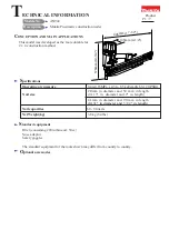
LOADING/UNLOADING THE TOOL

1.   Set the pin length adjustment switch 

to the appropriate setting for the 
length of pins you are loading by 
first pushing in on the red switch 
and sliding until the notch is in the 
appropriate groove.

2.   Push the latch button. Pull back on 

the magazine cover fully.

3.   Insert a stick of fasteners into the 

magazine with pins positioned as 
shown. Make sure pins are not dirty 
or damaged. Pins are marked for 
direction of loading.

4.   Push the magazine cover forward 

until latch engages.

5.   Always unload all fasteners before 

removing tool from service. 
Unloading is the reverse of loading, 
except always disconnect the air 
supply before unloading.

CLEARING A JAM FROM THE TOOL

1.   Disconnect the air 

supply from the tool.

2.   Remove all pins from the magazine 

(see "Loading/ Unloading The 
Nailer"). Failure to do so will cause 
the nails to eject from the front of 
the tool.

3.   Completely remove the two (2) small 

nose screws and the top nose plate 
to reveal the jammed fastener.

4.   Using caution not to bend or 

damage the driver blade, use a pick 
or some other pointed object to pry 
free and clear the jammed fastener.

USER-MAINTENANCE 
INSTRUCTIONS

TECHNICAL SERVICE

Please call our Tool Hotline at 1-800-
543-6400 with any questions regarding 
the operation or repair of this tool or 
for additional copies of this manual.

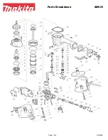
FASTENER AND REPLACEMENT 
PARTS


Use only headless 

  micropins, 23 gauge. 

Tool performance, safety and durability 
could be reduced if improper fasteners 
are used. When ordering replacement 
parts or fasteners, specify by part 
number.

DRIVER BLADE CARE AND 
REPLACEMENT

In order to properly drive the 
tiny micropins and leave a nearly 
undetectable hole, the tips of the driver 
blades end in a fine point and are 
therefore quite vulnerable to abuse and 
extended use.

To maximize the life of the blade, 
closely examine fasteners for defects. 
Make sure the pin length adjustment 
switch is properly set. Do not use 
defective or improper fasteners. Also 
load fasteners in the proper orientation; 
the pin points and the arrows always 
point toward the wood surface. Drive 
fasteners into wood products only (see 
"Loading/ Unloading The Nailer").

Even with good care, extended use 
of the tool may eventually lead to tip 
failure. Replacement driver assemblies 
can be purchased by calling 1-800-
543-6400 and refer to part number 
SKN11200AV.

Replace assembly by first removing the 
four (4) head cap screws using the 4mm 
hex wrench provided. Remove head cap 
and components to access the driver 
piston. Remove and replace driver 
assembly using your fingers. Replace 
components and head cap as removed.

TOOL REPAIR

Only qualified personnel should 
repair the tool and they should use 
genuine Husky replacement parts and 
accessories, or parts and accessories 
which perform equivalently.

150 psi or greater

Latch 
Button

Summary of Contents for HDN10500

Page 1: ...information observe the following symbols Danger indicates an imminently hazardous situation which if not avoided WILL result in death or serious injury Warning indicates a potentially hazardous situation which if not avoided COULD result in death or serious injury Caution indicates a potentially hazardous situation which if not avoided MAY result in minor or moderate injury Notice indicates impor...

Page 2: ...in moving parts c Avoid unintentional starting Be sure the switch is off before connecting to the air supply Do not carry the tool with your finger on the switch or connect the tool to the air supply with the switch on d Do not overreach Keep proper footing and balance at all times Proper footing and balance enables better control of the tool in unexpected situations 2 Operating Instructions Impor...

Page 3: ... d Disconnect the tool from the air source before making adjustments doing tool maintenance clearing jams leaving work area loading or unloading the tool Such precautionary measures reduce the risk of injury to persons e Store the tool when it is idle out of reach of children and other untrained persons A tool is dangerous in the hands of untrained users f Maintain the tool with care Keep a cuttin...

Page 4: ...ch will cause death or serious personal injury Use only a pressure regulated compressed air source to limit the air pressure supplied to the tool The regulated pressure must not exceed 100 psi If the regulator fails the pressure delivered to the tool must not exceed 200 psi The tool could explode which will cause death or serious personal injury SAVE THESE INSTRUCTIONS DO NOT DISCARD OPERATING INS...

Page 5: ... all pins from the magazine see Loading Unloading The Nailer Failure to do so will cause the nails to eject from the front of the tool 3 Completely remove the two 2 small nose screws and the top nose plate to reveal the jammed fastener 4 Using caution not to bend or damage the driver blade use a pick or some other pointed object to pry free and clear the jammed fastener USER MAINTENANCE INSTRUCTIO...

Page 6: ...ring must be coated with O lube before assembling A small amount of oil must be used on all moving surfaces and pivots After reassembling a few drops of 30W non detergent oil or equivalent must be added through the air line before testing STORAGE The tool should be stored in a cool dry place Interchange Information Can use 1 2 inch to 1 inch pins from the following branded 23 g micropinners Senco ...

Page 7: ...k of lubrication 6 Replace and lubricate o rings 7 Damaged O Ring on trigger valve 7 Replace o rings 8 Air leaks 8 Tighten screws and fittings 9 Cap seal leaking 9 Replace seal Tool runs slow or has loss of power 1 Tool not lubricated sufficiently 1 Lubricate nailer 2 Broken spring in cylinder cap 2 Replace spring 3 Exhaust port in cap is blocked 3 Replace damaged internal parts Fasteners are jamm...

Page 8: ...aser s abuse neglect or failure to operate products in accordance with instructions shall also include the removal or alteration of any safety devices If such safety devices are removed or altered this warranty is void D Normal adjustments which are explained in the owner s manual s provided with the product E Items or service that are normally required to maintain the product i e o rings springs ...

Page 9: ...ridas de gravedad Ésto le indica que hay una situación que PODRIA ocasionarle heridas no muy graves Ésto le indica una información importante que de no seguirla le podría ocasionar daños al equipo NOTA Información que requiere atención especial Instrucciones de Seguridad Importantes INSTRUCCIONES EN REFERENCIA AL PELIGRO DE INCENDIOS CHOQUE ELÉCTRICO O LESIONES PERSONALES Cuando se usen herramient...

Page 10: ...ien iluminada Los bancos desordenados y las áreas oscuras aumentan el riesgo de choque eléctrico incendio y lesiones personales b No haga funcionar la herramienta en entornos explosivos como por ejemplo cuando haya polvo líquidos o gases inflamables No lleve la herramienta con su dedo sobre el interruptor ni conecte la herramienta al suministro de aire con el interruptor en la posición de encendid...

Page 11: ...e activación de la herramienta adecuado tomando en cuenta la aplicación de trabajo para la cual se usa la herramienta Nunca limpie la herramienta con gasolina o ningún otro líquido inflamable Nunca use la herramienta en la cercanías de líquidos o gases inflamables Una chispa podría encender los vapores y ocasionar una explosión que podría ocasionarle la muerte o heridas graves No quite modifique n...

Page 12: ...miento o dentro del rango de presiones indicado en la herramienta Antes de usar la herramienta verifique siempre que el suministro de aire haya sido regulado a la presión de funcionamiento o esté dentro del rango de presiones indicadas b No use nunca oxígeno dióxido de carbono gases combustibles o ningún gas en botellas como suministro de aire para la herramienta Tales gases puede explotar y causa...

Page 13: ...ión de seguro sólo un jalón del gatillo puede disparar un sujetador Después de comprobar de que no hayan sujetadores en la herramienta verifique la seguridad del funcionamiento de la traba del gatillo activada para prevenir que la herramienta dispare un sujetador antes de guardarla Desconecte siempre la herramienta del aire comprimido cuando no esté en uso PARA CARGAR Y DESCARGAR LA HERRAMIENTA 1 ...

Page 14: ... para el conjunto de impulsión pueden comprarse llamando al 1 800 543 6400 refiera al número del repuesto SKN11200AV Sustituya el conjunto quitando primero los cuatro 4 tornillos de la cubierta de la cabeza principales usando la llave hexagonal de 4 mm que se proporciona Retire la cubierta y componentes de la cabeza para acceder al pistón de impulsión Con los dedos retire y reemplace el conjunto d...

Page 15: ...los anillos en O Lubríquelos 7 Los anillos en O de la válvula del gatillo están dañados 7 Debe reemplazar los anillos en O 8 Hay fugas de aire 8 Debe apretar los tornillos y las conexiones 9 El sello de la tapa tiene pérdidas 9 Reemplace el sello La herramienta funciona lentamente o pierde potencia 1 La herramienta no está bien lubricada 1 Necesita lubricar la clavadora 2 El resorte de la tapa del...

Page 16: ...suministrado también debe incluir la desconexión o modificación de los instrumentos de seguridad Si dichos instrumentos de seguridad son desconectados la garantía quedaría cancelada D Los ajustes normales explicados en el los manual es suministrado s con el producto E Artículos o servicios normalmente requeridos para el mantenimiento del producto tales como anillos en O resortes amortiguadores def...

Reviews: