background image

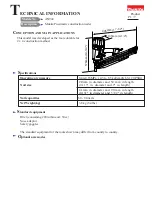
This model was developed as the more durable for
2 x 4 construction method.

Operating air pressure

 0.44-0.83MPa  ( 4.5 to 8.5 kgf/cm2G 65-120 PSIG) 

Nail size


4.1mm in diameter and 90 mm in length

Nail capacities

Net Weight(kg)

  Oiler (containing #90 turbine oil: 30cc)

Nose adaptor
Safety goggles

S

pecifications


S

tandard equipment

O

ptional accessories

C

ONCEPTION AND MAIN APPLICATIONS

Models No.

Product

T

ECHNICAL INFORMATION

 Description

376mm (14-3/4")

446mm (17-1/2")

108mm (4-1/4")

AN942

Makita Pneumatic construction nailer

The standard equipment for the tools shown may differ from country to country.

2.9

mm in diameter and 50 mm in length

(0.113" in  diameter and 2" in length)

60 - 84 nails

3.8 kg (8.4lbs)

 (0.131" in diameter and 3/1/2" in length)

P 1 / 7

Summary of Contents for AN942

Page 1: ...adaptor Safety goggles Specifications Standard equipment Optional accessories CONCEPTION AND MAIN APPLICATIONS Models No Product TECHNICAL INFORMATION Description 376mm 14 3 4 446mm 17 1 2 108mm 4 1 4...

Page 2: ...II Please refer to the following parts name Exhaust cover Top cap Housing Driver guide Contact arm Pusher lever Magazine Joint Inlet cap Trigger III The bolts have to be fastened as follows Bolt and...

Page 3: ...seat from head valve See Fig 3 Fig 1 Hex socket head bolts M6x25 4 pcs Hex socket head bolts M5x10 3 pcs Top cap Top cap Exhaust cover Fig 2 Head valve with valve seat O ring 40 and O ring 56 Compres...

Page 4: ...p cap gasket from housing And then remove trigger valve guide as illustrated in Fig 7 No 1 Spring pin 3 28 No 2 Spring pins 3 28 Trigger Fig 6 Fig 7 Fig 8 Trigger valve case Trigger valve stem Compres...

Page 5: ...joint has to be fastened loosely at the first Finally it has to be tightened firmly Fig 9 Fig 10 Contact arm Driver guide Magazine section 6 Mounting driver complete Pass driver complete through driv...

Page 6: ...Check or replace the following parts See Fig 14 O ring 3 O ring 12 O ring 8 O ring 18 D Leaking from the joint of inlet cap and housing Check or replace the following parts See Fig 15 Inlet cap gasket...

Page 7: ...Repair P 7 7 A B C D E Fig 11 Fig 16 O ring 87 O ring 60 E Leaking from the top of driver guide See Fig 16 O ring 87 on cylinder separator O ring 60 on cylinder Cylinder separator Cylinder...

Reviews: