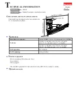
Makita AN942, Technical Information
The Makita AN942 is a high-quality parts breakdown manual for all your DIY needs. With detailed diagrams and step-by-step instructions, this valuable resource allows you to effortlessly repair and maintain your Makita AN942. Download this manual for free at manualshive.com and unlock the full potential of your Makita AN942.
Share
Download


Reviews:
No comments
Related manuals for AN942

42.578.10
Brand: EINHELL Pages: 40

HP 07
Brand: UES Pages: 22

FN001GA202
Brand: Makita Pages: 76

NV 50A1
Brand: Hitachi Pages: 72

NR 83A2 (S1)
Brand: Hitachi Pages: 60

NT 32AE2 (S)
Brand: Hitachi Pages: 84
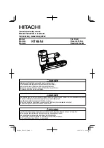
NT 65A5
Brand: Hitachi Pages: 68

NR 90AD (S)
Brand: Hitachi Pages: 68

NR 38AK
Brand: Hitachi Pages: 60

NR 83A3
Brand: Hitachi Pages: 60

NT 65MA2
Brand: Hitachi Pages: 84

NV 75AN
Brand: Hitachi Pages: 72

NC 50H
Brand: Hitachi Pages: 48

NR 90AF (S1)
Brand: Hitachi Pages: 64

N3804AB3(S)
Brand: Hitachi Pages: 60

NR 1890DC
Brand: Hitachi Pages: 92

NR 83AA2
Brand: Hitachi Pages: 44

NR 90GC2
Brand: Hitachi Pages: 76


