


PD2794 02/2017
Page 2
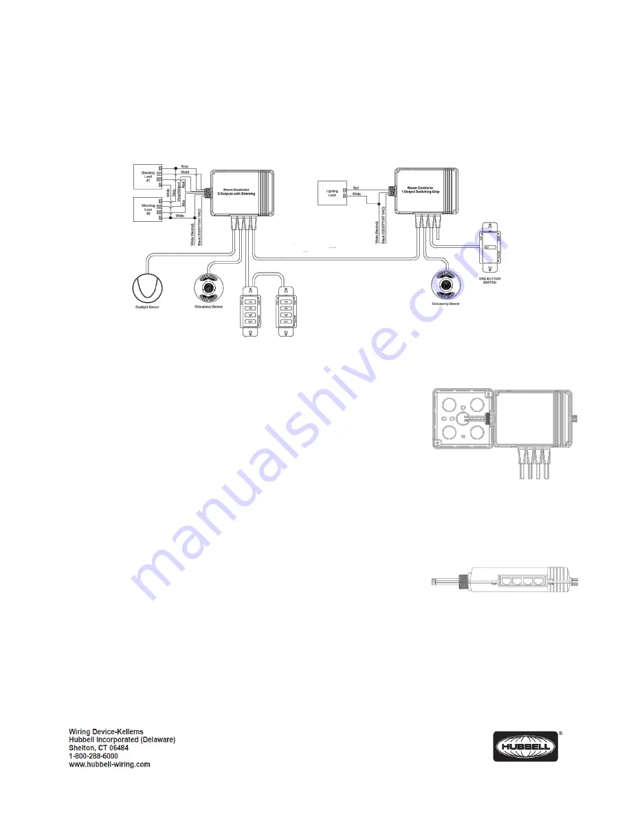
Figure 1
Room Controller mounted
into a 4 x 4 junction box
Figure 2
Room Controller RJ45 ports
to connect control devices
Description
Hubbell Wiring Device-Kellems Load:Logic
®
Room Controller is a smart device designed to control and manage lighting loads in
a space based on a set of configured parameters. It contains two independently controlled outputs. Optional 0-10VDC outputs
are available for controlling dimmable ballasts and LED drivers. The Load:Logic
®
Room Controller also features four RJ45 ports
that provide plug and play support for occupancy, daylight sensors and switches for local control. The Load:Logic
®
Room
Controller can operate in a stand-alone mode or connected with other room controllers.
Installation
1. DO NOT DISCARD THE MAC ADDRESS LABELS INCLUDED WITH THE
PRODUCT. SEE STEP (5) BELOW.
2. The room controller has a MAC address label affixed to the outside of the unit.
Place the enclosed MAC address label(s) in a log book and record the location of
the room controller and the circuit(s) it controls. The MAC address will be needed
later during the system setup process.
3. Turn power OFF at the service panel.
4.
Mount the room controller’s enclosure to a ½” knockout opening of an electrical junction box.
Secure it to box tightening the included locknut. (See Figure 1)
5. Connect the control devices (e.g. occupancy sensors, daylight sensor and switches) to
any of the RJ45 ports available using a UTP patch cord. Similar devices (e.g. switches or
occupancy sensors) may be connected together from the same RJ45 port. (See Figure 2)
6. Make the appropriate electrical connections from the room controller to the corresponding
devices as shown in Figure 3.
7. Turn ON the power at the service panel.
8. Test the installation as follows:
a. Momentarily press Button A to toggle Load A (red wire) ON and OFF.
b. Momentarily press Button B to toggle Load B (blue wire) ON and OFF.
c.
Turn ON Load A.
d. Press and hold Button A down to decrease the light level on Load A.
e. Release Button A and press again to increase the light level on Load A.
f.
Turn OFF Load A.
g. Turn ON Load B
h. Press and hold Button B down to decrease the light level on Load B.
i.
Release Button B and press again to increase the light level on Load B.
j.
Turn OFF Load B.


