


PD2795 02/2017
Page 2
Mode
: Indicates how the relay will respond to the occupancy sensor. Occupancy mode is automatic ON. Vacancy mode is
manual ON. This will automatically be set to Vacancy mode for all relays if at least one switch is connected to the room
controller(s).
Occupied
: Sets the state of the relay when the room is occupied. Default is ON.
Unoccupied
: Sets the state of the relay when the room is unoccupied. Default is OFF.
Groups
: A blue background fill in one of the 16 available groups indicates that this relay is selected to be a member of this
group number. A gray background fill indicates that the relay is NOT a member of the group. The relay may be a member
of any or all groups if required.
Relay
: Allows manual ON/OFF actuation of the relay in real time.
Make changes as needed. Touch the <
Accept
> button to save the changes or touch the <
Back
>
button to exit WITHOUT saving the changes.
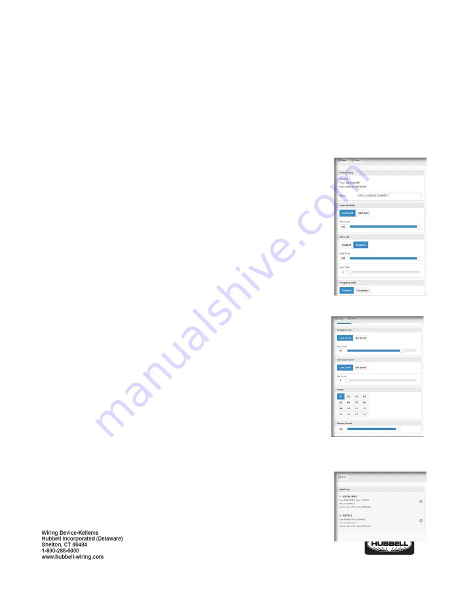
3.
Dimmers
: Touch to display a list of dimmers found in the room. Touch one of the dimmers to
see a display of the dimmer settings:
Name
: Allows the dimmer to be given a meaningful name. Use the keyboard to enter a
name if desired.
Power Up
: Select the state this dimmer will default to upon restoration after an outage.
<
Last State
> is the default setting. Touch <
Set Level
> to enter a specific dim level for
power up. Use the <
Level
> slider to set the desired level or, touch the box to use the
keyboard to enter the level.
High Trim
: Sets the maximum dimming level for this dimmer. The default setting is 100%.
Low Trim
: Sets the minimum dimming level for this dimmer. The default setting is 0%
Dim to OFF
: If set to <
Enabled
>, a relay(s) in the same group as the dimmer, will turn
OFF when the dimming level reaches 0%. If set to <
Disabled
>, a relay(s) in the same
group as the dimmer, will NOT turn OFF when the dimming level reaches 0%.
Mode
: Indicates how the dimmer will respond to the occupancy sensor. Vacancy Mode
is Manual ON. Occupancy Mode is Automatic ON.
Occupied Level
: Sets the Level of the dimmer when the room is occupied. Default is
Last Level
.
Unoccupied Level
: Sets the level of the dimmer when the room is unoccupied. Default
is
Last Level
.
Groups
: A blue background fill in one of the 16 available groups indicates that this
dimmer is selected to be a member of this group number. A gray background fill indicates that the dimmer is NOT a
member of the group. The dimmer may be a member of any or all groups if required.
Dimmer
: Allows manual actuation of the dimmer in real time.
Make changes as needed. Touch the <
Accept
> button to save the changes or touch the <
Back
>
button to exit WITHOUT saving the changes.


