


PD2795 02/2017
Page 4
C.
Scene Switch
:
Name
: Allows the switch to be given a meaningful name. Use the keyboard to enter a name as desired.
Preset Setup
: The buttons are factory configured to control Preset 1 - Preset 4 from top to bottom respectively. Use the
drop down arrow adjacent to a button to choose one of the 16 available presets to be recalled by this button.
Preset Status
: Indicates the currently activated preset.
Raise/Lower Setup
: Allows adjustment to the speed at which the dimming level will change as a Raise or Lower button
held down.
Rate
: Sets the rate at which level change messages are sent from the switch to the dimmer. Recommended setting is
300.
% Change
: Sets the amount of change that occurs with each message. A setting of 10 will provide about a 5 second
transition time from 0% to 100% while holding down a Raise or Lower button.
Make changes as needed. Touch the <
Accept
> button to save the changes or touch the <
Back
> button to exit WITHOUT saving
the changes.
5.
Occupancy Sensors
: Note that regardless of the quantity of sensors installed, the App will only indicate a single sensor with a
composite occupancy state for the room.
Name
: Allows the sensor to be given a meaningful name. Use the keyboard to enter a name as desired.
Groups
: A blue background fill in one of the 16 available groups indicates that this sensor is selected to be a member of
this group number. A gray background fill indicates that the sensor is NOT a member of the group. By default, the
occupancy sensor is set to be a member of all groups.
State
: Indicates the Occupied or Unoccupied state of the room as reported by the occupancy sensor at the time the App
screen was accessed. This is read only. Touch the <
Refresh
> button to re-read the occupancy state of the room.
Make changes as needed. Touch the <
Accept
> button to save the changes or touch the <
Back
> button to exit WITHOUT saving
the changes.
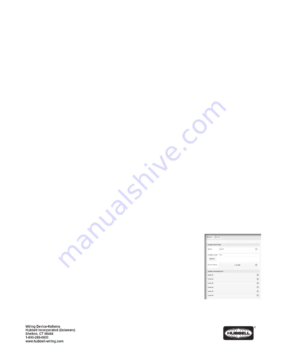
6.
Daylight Sensor
: Touch to display the
Photocell
set up page. This page allows for the setup of up to 6 zones of daylight
harvesting using a single compatible photocell like the RCDP.
Name
: Allows the sensor to be given a meaningful name. Use the keyboard to enter a
name as desired.
Daylight Level
: Indicates the current amount of daylight visible to the daylight sensor.
Touch <
Refresh
> at any time to re -read the daylight level.
Sensor Range
: Use the pull down to select the range appropriate to the daylight sensor
model installed. The standard RCDP daylight sensor is factory set to 3 to 300. This is the
nominal default for typical indoor side lighted applications.
Zone #
: Use the pull down to select the type of daylight harvesting control to be used for
this zone. The available choices are:
A.
None
: Daylight harvesting not enabled. This is the default setting for Zones 2-6.


