Hubbell Load:Logic Installation Instructions Manual Download Page 2


  PD2795                                 02/2017 

                                                                                                                                  Page 1 

Room Controller Setup App 

Operation Guide 


IMPORTANT

: This App is designed to assist in the configuration of control parameters for the Hubbell Wiring Device-Kellems 

Load:Logic

®

 Room Controller.  Once the App has been used to change any setting in a room, manual configuration using the push 

buttons and LEDs on the Room Controller will be disabled. All further settings will need to be made using the App. (See Room 
Controller Installation Instructions)   
 

START THE APP BY TOUCHING THE NX SCREEN ICON. 

 
When the App starts, you will be prompted to enter a security pin.  The default pin is 

96@01

.  

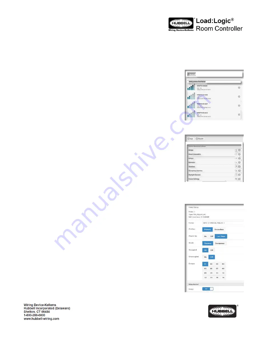
Once started, the App will automatically do a discovery to find all active 

RCBTM’s (NXBTR) 

Bluetooth

®

 interface modules that are in range.  After discovery is complete, a list of discovered 

RBTM’s will be displayed.  Use the signal strength indicators to determine the closest module for 
the current room.  Modules can also be uniquely identified by the MAC address label on the 
module’s housing. 
 
Touch the appropriate module indicator to start a discovery of devices in the room where this 
module is installed.  Wait for the discovery to complete before making further selections. 
 
When discovery is complete, a listing of the devices found will be displayed.  These will include: 
 
1. 

Room Controllers

: Touch to display a list of room controllers found in the room.  Touch 

one of the room controllers to see a display showing controls for the relay(s) and 
dimmer(s), if present, in that room controller.  If the room has only one room controller, it 
will automatically open when 

Room Controllers

 is selected. 

 
The current state of the relays and dimmers will be displayed on the screen.  The displays are in 
real time.  
 
Use the relay control(s) to change the state of the relay.  Use the dimmer control bar to change 
the state of the dimmer(s) 
 

Reboot

 (Top of Screen): Restarts the room controller. 

Factory Reset

: Sets the room controller and all connected devices back to factory 

default settings. 

 
2. 

Relays

: Touch to display a list of relays found in the room. Touch the relay to see a display 

of the available relay settings. The current settings will be shown on the display. 


Name

: Allows the relay to be given a meaningful name. Use the keyboard to enter a 

name if desired. 


Pri/Sec

: Indicates whether this relay is logically a Primary relay or a Secondary relay.  

This logic is used with the daylight sensor option to determine the sequence in which 
the relay(s) will switch OFF in response to increasing daylight.  The Primary relay will 
switch first, followed by the Secondary. 
 

Power Up

: Select the state this relay will default to upon restoration of power to the 

room controller after an outage. The default setting is 

Last State


Summary of Contents for Load:Logic

Page 1: ...unit For Indoor use only Do not use outdoors Disconnect switch or a circuit breaker must be provided and marked as the disconnecting device The use of accessory equipment not recommended by the manuf...

Page 2: ...splayed These will include 1 Room Controllers Touch to display a list of room controllers found in the room Touch one of the room controllers to see a display showing controls for the relay s and dimm...

Page 3: ...ion after an outage Last State is the default setting Touch Set Level to enter a specific dim level for power up Use the Level slider to set the desired level or touch the box to use the keyboard to e...

Page 4: ...Groups A blue background fill in one of the 16 available groups indicates that this switch is selected to be a member of this group number A gray background fill indicates that the switch is NOT a me...

Page 5: ...ne of the 16 available groups indicates that this sensor is selected to be a member of this group number A gray background fill indicates that the sensor is NOT a member of the group By default the oc...

Page 6: ...urned OFF NOTE Make adjustments to the Design Level until the desired foot candle reading is achieved on the light meter at the task surface E Test Mode This is the factory default setting for Zone 1...

Page 7: ...rcuit s it controls The MAC address will be needed later during the system setup process 3 Turn power OFF at the service panel 4 Mount the room controller s enclosure to a knockout opening of an elect...

Page 8: ...Occupancy sensor with RP option 4 Loads NOTE Only one daylight sensor can be connected in each room zone Self Configuration The room controller s sequence of operation will automatically reconfigure...

Page 9: ...s RCSNFx and RCSTOx RCSRLx RCSSCx RCSNRLFx will self configure by default to their respective descriptions For example RCSRLx is a Raise Lower dimmer Its default operation will be to change ALL the li...

Page 10: ...2 Observe that the button is located slightly offset from the bezel opening The LED marked SVC will blink while the configuration button is being pressed 3 Release the configuration button and note t...

Page 11: ...Simultaneously press and hold buttons A and B for three seconds until LED A begins to blink rapidly This indicates the room controller has transitioned from load configuration mode into photocell con...

Page 12: ...n is complete the room controller will automatically exit configuration mode and return to normal operation Daylight harvesting will now be active based on the settings made during configuration Reset...

Reviews: